9
AMC‑15
7.
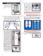
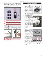
Connect the power cord to the power inlet
A
on the rear of
the cart, then plug the other end of the power cord into a
grounded electrical outlet of the proper voltage correspond-
ing to the unit version (115V or 230V). Turn the main power
switch
B
to the ON (I) position.
B
A
WARNING:
Do not connect the power cord to the AMC-15
in the presence of anesthetics or flammable gases.
CAUTION:
Do not connect 230V power to a 115V unit to
avoid circuit breaker damage not covered under warranty.
8.
ACCESSORY TRAY —
To install the
optional
accessory tray,
insert the post
A
into the holder on the top lid of the cart.
Use the included 3/16” hex wrench to adjust the height of
the pivot block
B
. Place the end of the arm
C
onto the pivot
block, then place the tray on the other end of the arm.
C
B
A
WARNING:
Maximum weight capacity of the accessory
tray is: 10 lb (4.5 kg)
SYSTEM OPERATION
1.
FOOT CONTROL —
Press
the foot pedal
A
to acti-
vate the working hand-
piece. Handpiece speed is
controlled by how far down
you press the foot pedal. To
enable water coolant to be
activated with the foot pedal,
toggle the water coolant
switch
B
towards the dot
C
on the foot control, as shown.
Toggle the switch away from
the dot to disable water coolant.
2.
INSTRUMENT HOLDERS —
Each instrument holder (except
the syringe holder) provides
an on/off toggle switch
A
and an automatic instrument
shut-off switch
B
. The toggle
switch must be ON (towards
the dot
C
, as shown) and the
instrument must be out of the
instrument holder to operate
the instrument. (NOTE: Turn
toggle switches OFF to ensure
that any instruments that may
not be fully seated in their
holders will not turn ON acci-
dentally when the foot pedal
is activated.)
3.
DRIVE AIR —
Pneumatic handpiece air pressure should be
adjusted to the pressure
recommended by the man-
ufacturer. To determine the
current pressure setting, lift
the handpiece from the HP-1
instrument holder and press
the foot pedal while looking
at the handpiece pressure
gauge
A
on the front panel.
If adjustment is necessary,
lift the top lid on the AMC-15
cart and lock the hinge in the
open position. Rotate the
HP 1 adjustment screw
B
counterclockwise to increase
pressure or clockwise to decrease pressure. Repeat this proce-
dure for the HP-2 handpiece using the HP 2 adjustment screw
C
and for the LOW SPEED handpiece using the LOW SPEED HP
adjustment screw
D
. The 2 remaining screws (
E
and
F
) are
not used.
B
A
C
A
B
C
B
C
D
E
F
A
Summary of Contents for AMC-15
Page 1: ...OPERATION MAINTENANCE MANUAL AMC 15 Mobile Dental Cart...
Page 17: ...17 AMC 15 NOTES...
Page 18: ...18 AMC 15...
Page 19: ...19 AMC 15...

