8.
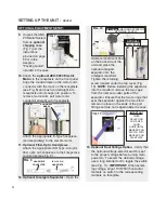
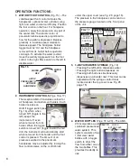
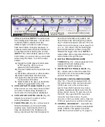
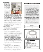
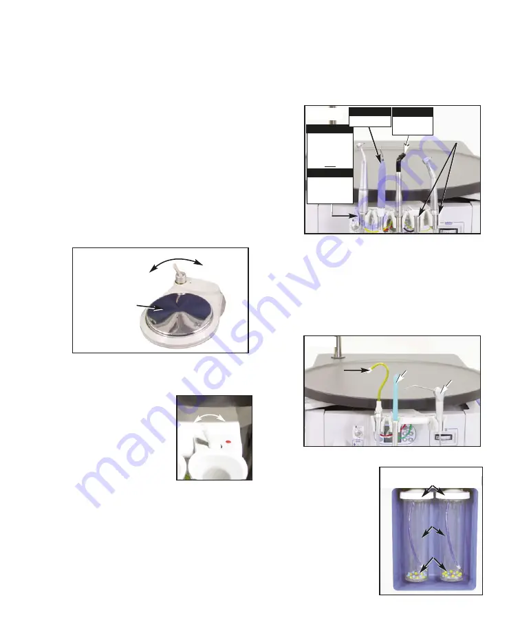
1. WET/DRY FOOT CONTROL
(Fig. 15) – The
variable-speed foot control activates the
handpieces, optional scaler, optional curing
light, and water coolant on/off spray. Position
the foot control on the floor. For handpiece
operation, apply foot pressure to any part of
the center disk. The electric motor or
pneumatic turbine speed is proportional to
how far the pedal is depressed. Depress
gradually to increase speed; release to
decrease speed. The handpiece holder
toggle must be 'On' and the handpiece
removed from its holder before operation
can begin. To activate the water coolant,
move the wet/dry toggle switch on the foot
control to the right. Move switch to the left to
disable water.
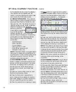
2. INSTRUMENT CONTROLS
(Figs. 16 & 17)
The Aseptico AMC-20 includes controls for
all handpiece and instrument holders. Each
holder includes an
On/Off toggle switch (see
Fig. 16) which when
turned 'Off' (toggle to the
left), keeps the
instrument off, even
when removed from its
holder. When the toggle
switch is turned 'On' (toggle toward the red
dot), the instrument will automatically start
when removed from its holder and the foot
control is pressed. The amount of air
pressure supplied to the pneumatic
handpieces may be adjusted by turning the
flow control screws on the control block
OPERATION FUNCTIONS:
APPLY
PRESSURE TO
ACTIVATE
HANDPIECE
WATER
OFF
WATER
ON
FIG. 15
under the upper cover (see Fig. 29, page 15).
The pressure to the handpiece can be read on
the pressure gauge located on the front panel
of the unit.
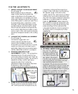
3. 3-WAY AIR/WATER SYRINGE
(Fig. 18)
• Pressing the left button dispenses water.
• Pressing the right button dispenses air.
• Pressing both buttons simultaneously
dispenses an air/water mist. This mist can be
adjusted with the syringe control block
located under the top cover (see Fig. 28,
page 15).
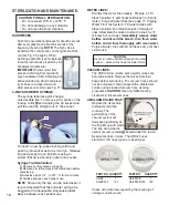
4. WATER BOTTLES
(Figs. 19 & 20) - The AMC-
20 incorporates a self-
contained pressurized
water system. This
system consists of two
1-liter clear water
bottles with a toggle
switch to direct the
flow from either one of
the two bottles. This
provides the ability to
use
FIG. 17
AIR
HANDPIECE
CONTROLS
(2)
OPTIONAL
3RD AIR
HANDPIECE
CONTROL
OR
OPTIONAL
ELECTRIC
HANDPIECE
CONTROL
OPTIONAL
OPTIONAL
OPTIONAL
CURING
LIGHT
OPTIONAL
OPTIONAL
SCALER
OPTIONAL
FIG. 18
SYRINGE
SALIVA
EJECTOR
HIGH VACUUM
(HVE)
FIG. 16
ON
OFF
FIG. 19
LEVEL INDICATORS
WATER BOTTLES
WATER
BOTTLE CAPS

