9.
different solutions (
NOTE:
The yellow and
blue floating level indicators can be used
to identify bottle contents when two
different types of fluids are used. Always
flush lines before changing solutions). A
pressure relief valve allows both bottles to
be replaced without draining the air tank.
(
NOTE:
This valve releases pressure from
both bottles; you cannot remove one bottle
while using the other). To refill the water
bottles:
a.)
Toggle the bottle pressure relief valve
to 'Off' (see Fig. 20) to remove
pressure from both bottles.
b.)
Unscrew bottles and remove from their
caps.
c.)
Fill bottles with water or other solution.
d.)
Screw bottles back into their caps.
e.)
Toggle the pressure relief valve to 'On'
to pressurize both bottles.
f.)
Select bottle to be used via the Bottle
Selector Toggle Switch (Fig. 20).
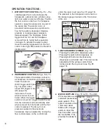
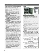
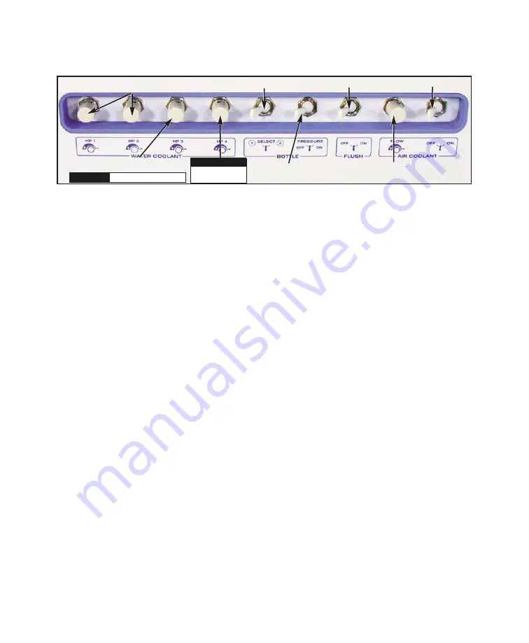
5. COOLANT AIR TOGGLE VALVE
(Fig. 20)
When turned on, this valve allows coolant
air to flow to the working handpiece or
motor when the foot pedal is depressed.
6. COOLANT AIR CONTROL VALVE
(Fig. 20)
Adjusts the volume of coolant air to the
working handpiece or motor.
7. FLUSH TOGGLE
(Fig. 20) – Allows user to
flush the handpiece or motor with water,
washing away contaminants which may
have accumulated in the handpiece and
tubing. User should flush the handpiece for
about 5 seconds after every patient, and
about 20 seconds at the beginning of each
day. To flush a handpiece, remove it from its
holder and point the spray nozzle away from
you, i.e., into a basin. Flip the flush toggle
and hold the desired number of seconds.
Release the toggle when done.
NOTE:
If
water bottles drain empty when flushing, air
will be flushed through the lines.
8. BOTTLE PRESSURE RELEASE
TOGGLE
(Fig. 20) – Allows pressure to be
released from both bottles while
maintaining system pressure.
9. WATER BOTTLE TOGGLE VALVE
(Fig.
20) – Allows user to direct the water flow
from either one of the two bottles (toggle
points to the bottle in use).
10. HIGH AND LOW VOLUME VACUUMS
(Fig. 18) – The unit is equipped with a 5-
liter waste tank, a high volume evacuator
(HVE) hose, and a low volume saliva
ejector hose. Both high and low volume
systems operate simultaneously from the
same vacuum source. To gain vacuum on
the HVE, fully open the HVE valve and
close the low volume valve. To gain
vacuum on the low volume valve, close the
HVE and open the low volume to full open.
11. CENTRAL VACUUM KIT
– Used with the
vacuum system and contains a disposable
solids collector. The system is located
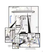
under the top cover (see Fig. 14, page 7).
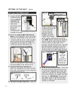
FIG. 20
COOLANT AIR TOGGLE
COOLANT AIR CONTROL VALVE
FLUSH TOGGLE
BOTTLE PRESSURE
RELEASE TOGGLE
BOTTLE SELECTOR TOGGLE
COOLANT FOR AIR HANDPC #3
OR
COOLANT FOR
AIR HANDPCS #1 & #2
OPTIONAL
SCALER
COOLANT
OPTIONAL
OPTIONAL ELECTRIC HANDPC
OPTIONAL

