15.
ROUTINE ADJUSTMENTS:
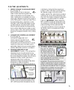
controlled by turning the flow adjustment
screws on the control block and monitoring
the pressure gauge on the front of the
system cabinet. The control block is located
under the top cover, behind the barrier wall
(Fig. 29). Turn screws clockwise to decrease
pressure or counterclockwise to increase
pressure.
IMPORTANT:
Always adjust the
HP1 and HP2 handpieces' pressures to the
manufacturer's recommended settings. The
pressure settings for the optional scaler,
curing light and electric motor are preset at
the factory and do not require any further
adjustments.
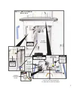
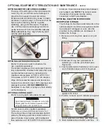
FIG. 29
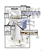
1. WATER COOLANT FLOW ADJUSTMENT
(Fig. 20, page 9)
Each handpiece has an individual
water control valve that regulates the
water coolant flow to the handpiece and
motor. Install and run a handpiece at a mid-
ange speed. Make sure the wet/dry toggle is
in the "ON" position on the foot control. Turn
the appropriate water coolant flow control
clockwise, until it seats softly. Begin turning
counterclockwise until a fine mist is visible.
This will provide excellent cooling while the
bur is cutting. (Note that each water coolant
control valve on the control panel controls its
respective handpiece located on the rotating
arm.)
2. COOLANT AIR CONTROL ADJUSTMENT
(Fig. 20, page 9)
A coolant air toggle valve and
control valve are provided to turn
coolant to the handpiece and motor
On and Off, and to control the flow. Turn the
coolant air control valve clockwise until it
seats softly. Begin turning counterclockwise
until the desired amount of air is achieved.
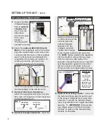
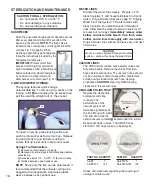
3. SYRINGE AIR/WATER FLOW
ADJUSTMENT
(Fig. 28) – The syringe flow
adjustment block is located under the top
cover, behind the arm barrier wall. There are
two slotted adjustment screws: the left screw
adjusts the air flow and the right screw
adjusts the water flow. Turning the
adjustment screws clockwise will decrease
the pressure, while turning them
counterclockwise will increase the pressure.
4. HANDPIECE PRESSURE ADJUSTMENT
The amount of air pressure supplied to the
HP1 & HP2 pneumatic handpieces may be
FIG. 28
WATER FLOW
ADJUSTMENT
SCREW
AIR FLOW
ADJUSTMENT
SCREW
FLOW ADJUSTMENT SCREWS (5)
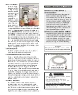
5. OPTIONAL WASTE FLOW ADJUSTMENT
(Fig. 30) The optional
waste flow valve controls
the waste water flow rate.
The valve is located in the
rear waste compartment.
Turn the lever as shown to adjust the flow
rate as specified by your State or County
laws regarding disposal of dental
wastewater. The small circle on the flow
indicator represents a 1-liter per minute flow
setting for the specific amalgam separator
provided with this AMC-20 Cart. An optional
bypass filter is available for areas where
amalgam separators are not required.
WASTE FLOW
ADJUSTMENT
VALVE
OPTIONAL
BYPASS
FILTER
FIG. 30
OPTIONAL EQUIPMENT ADJUSTMENTS:
OPTIONAL

