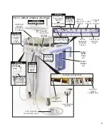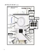
4.
9.
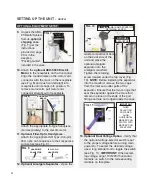
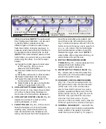
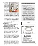
Unpack the AMC-
20 Dental System
from its
optional
shipping case
(Fig. 7) per the
instructions
provided on page
20 or in the
Aseptico
"Packing Guide",
included in the case.
10.
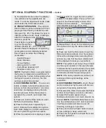
Attach the
optional AEU-5000 Electric
Motor
to the receptacle on the front panel.
Align the round dimple on the motor cord
connector with the mark on the receptacle
(see Fig. 8) and push cord straight into
receptacle until it snaps into position. To
remove motor/cord, pull motor cord
connector straight out of receptacle.
Attach the appropriate E-Type handpiece
(sold separately) to the electric motor.
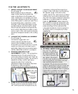
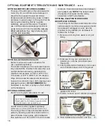
11. Optional Fiber-Optic Handpieces
-
Attach the appropriate ISO Type-C (6-pin)
fiber optic air handpieces to their respective
connectors (see Fig. 9).
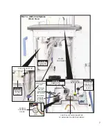
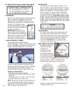
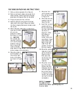
12. Optional Amalgam Separator -
Open the
waste compartment door
on the back side of the
unit and place the
optional amalgam
separator into the
amalgam manifold.
Tighten the retaining
screw located under the top cover (Fig.
10).
NOTE:
Before installing the separator
into the manifold, remove the two caps
from the inlet and outlet ports of the
separator. Ensure that the two O-rings that
seal the separator against the mani-fold
remain in place on the ends of the port
fittings and are not lodged inside the caps.
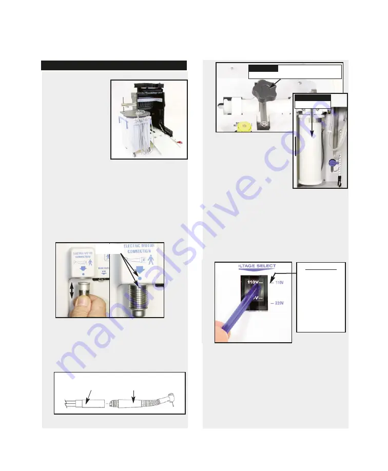
13. Optional Dual Voltage Option
- Verify that
the optional voltage-selector switch is set
to the proper voltage before turning main
power On. To select the desired voltage,
use a long slender tool to toggle the switch
(see Fig. 11).
IMPORTANT:
When select-
ing voltage, align 110V/220V horizontal
markers on switch to the corresponding
markers on faceplate.
SETTING UP THE UNIT -
Cont’d
FIG. 7
ALIGNMENT
MARKS
FIG. 8
FIG. 11
FIG. 10
OPTIONAL AMALGAM SEPARATOR
RETAINING SCREW
OPTIONAL
SEPARATOR
OPTIONAL EQUIPMENT SETUP:
IMPORTANT
WHEN
SELECTING
VOLTAGES,
ALIGN
HORIZONTAL
MARKERS ON
SWITCH WITH
MARKERS ON
FACEPLATE
OPTIONAL
OPTIONAL
ISO-C 6-PIN
HANDPIECE
HANDPIECE
CONNECTOR
FIG. 9

