Page 8
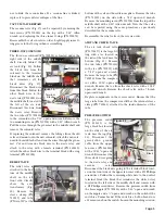
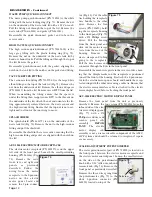
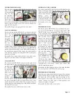
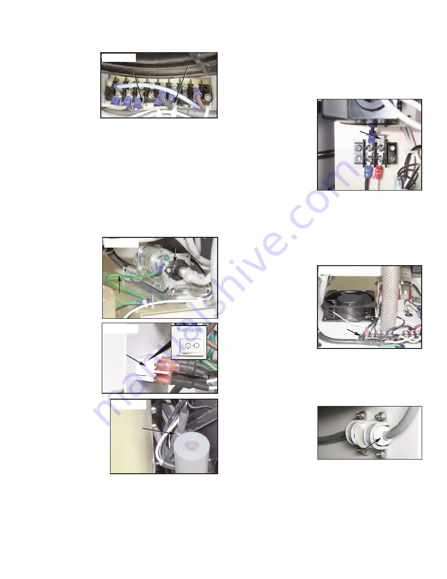
ISOLATED HIGH-VOLTAGE TERMINAL BLOCK
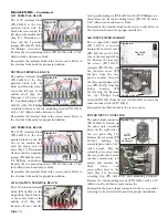
This terminal block
(PN 860256) is located
on the lower right side
of the chassis base,
under the pressure
end of the compressor
(Fig. 33). Remove all
the wires going to the
terminal block with a #2 Phillips screwdriver. Remove the
two mounting nuts (PN 510395) with a 5/16" open-end
wrench, then remove block and insulator (PN 461971). Note
positions of the 3-position and 2-position jumpers (PNs
860253 & 860254 respectively), then remove jumpers from
the old terminal block and attach to the new block.
Reassemble the terminal block in the reverse order, referring
to the electrical schematic for proper installation.
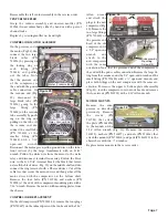
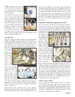
WASTE PUMP
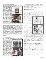
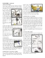
Remove the green/yellow ground wire from the pump (PN
730271) with a ¼"
wrench (Fig. 34). On
the back side of the
cart, remove the eight
screws (PN 510160)
that attach the power
outlet assembly with a
5/64" Allen wrench.
Follow the white (PN
870031) and black (PN
870026) wires from the
pump to the white
rocker switch (PN
830108) on the power
outlet assembly (Fig.
35). On the black wire,
there is a large section
covered by heat shrink
that encloses a wire con-
nector (Fig. 36). Peel this
heat shrink back, on the
pump side of the connec-
tor, and discon-nect the
female terminal. Follow
the other white wire to
the rocker switch and remove the terminal at that location.
Cut the cable ties that secure the tubing to the pump ends
and remove both clear tubes (PN 730288) from the pump.
Leave the reducers (PN 730627) attached to the tubes.
Remove the four mounting screws (PN 510404) from the
pump with a 3/32" Allen wrench. Carefully feed the pump
wires through the grommet in the middle shelf and remove
the pump.
Reassemble the waste pump in the reverse order, referring to
the electrical schematic for the proper installation.
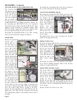
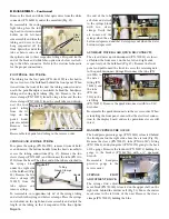
COOLING FAN TERMINAL BLOCK
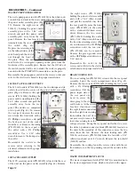
The cooling fan terminal block (PN 860255) is located on the
vertical wall of the pump support bracket (PN 461864) (Fig.
37). Remove the wires
going to the terminal block
with a #2 Phillips screw-
driver. Note position of
jumper (PN 860254) and
remove from block.
Remove the terminal
block and insulator (PN
461973) with a 5/64" Allen
wrench. Attach jumper to
the new block.
Reassemble in the reverse order, referring to the electrical
schematic for proper installation.
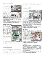
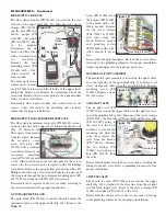
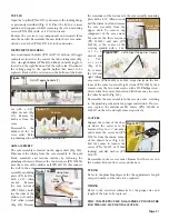
INNER COOLING FAN
The inner cooling fan (PN 540012) is located on the middle
shelf (Fig. 38). Follow the white and black wires from the fan
to the terminal blocks on
the left side of the shelf
and remove from block
with a #2 Phillips screw-
driver. Remove the four
screws (PN 510160) hold-
ing the fan with a 5/64"
Allen wrench. Remove
fan.
Reassemble fan in the reverse order with the air flow indica-
tor on the fan pointing downward. Refer to the electrical
schematic for proper installation.
WASTE PUMP CONTROL VALVE
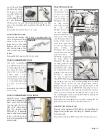
This pump control valve
(PN 730609) is located on
the inboard wall of the
waste container shield (PN
461742), above the inner
cooling fan (Fig. 39).
Remove the two tubes (PN 730312) going to the valve by
pushing in on the white rings and pulling the tubes out of the
valve. Remove the two retaining clamps (PN 510686) with an
11/32" wrench.
Replace control valve in the reverse order.
GND Wire
Waste Pump
Jumper
Figure 34
Figure 37
DISASSEMBLY - Continued
Figure 33
3-Pos Jumper
2-Pos Jumper
Figure 36
Figure 35
Rocker
Switch
Wire
Connector
(Under
Heatshrink)
Figure 38
Fan
Terminal
Block
Figure 39
Locking Ring

