Page 9
WASTE SENSOR CONNECTOR
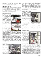
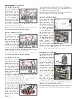
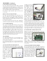
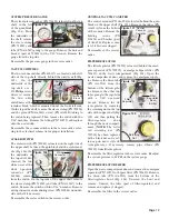
The waste sensor connec-
tor (PN 860080) is located
on the inboard side of the
waste shield (Fig. 40),
above the large vacuum
tube (PN 730608). Follow
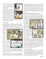
the two wires (PNs 870026
& 870031) going to the
terminal block (PN
860241) under the upper
shelf (Fig. 41) and remove
wires with a #2 Phillips
screwdriver. Remove the
nut on the inboard side of
the connector with a 9/16" wrench and then pull the connec-
tor out through the outboard side of the waste shield, from
the waste compartment.
Reassemble the waste sensor connector in the reverse order.
Refer to electrical schematic for proper installation.
AEU-5000 POWER BOARD
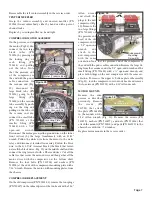
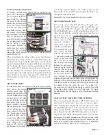
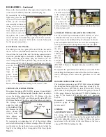
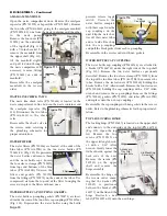
The AEU-5000 power
PCB board (PN 330565-
C) is located on the left
inboard side of the waste
shield
(Fig.
42).
Disconnect the cables
going to the board.
Remove the sleeve clamp
(PN 461607) and tube (PN
730227) going to the
board with a pair of nee-
dle-nose pliers. Remove
the board mounting screw
with a #2 Phillips screw-
driver.
Reassemble power board
in the reverse order, refer-
ring to electrical and
plumbing schematics for proper installation.
IMPORTANT:
The AEU-5000 power PCB board is not a user-serviceable
component of the AMC-20CF system and should be
returned to Aseptico if repairs are necessary.
AEU-5000 POWER SUPPLY
The AEU-5000 power supply (PN 330570) is located direct-
ly above the AEU-5000 power board (Fig. 42). Disconnect
the three-pin connector with the red and black wire at the
power board. Cut the cable tie going to the other tie that
wraps around the power cord and remove the power cord
from the supply. Cut the remaining cable ties around the
power supply and remove the supply from its Velcro pad.
Remove the two cable tie pieces from their cable-tie holders
and replace with new ties.
Reassemble power supply in the reverse order.
AEU-5000 POWER CORD
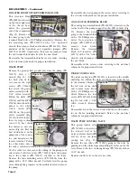
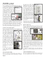
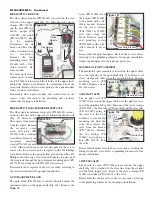
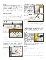
Cut the cable tie at
the power supply as
described above
and remove the
power cord plug
(Fig. 43). Follow
the black and white
wires from the
power cord to their
respective terminal
blocks on the mid-
dle shelf and
remove wires with a #2 Phillips screwdriver. Follow the solid-
green ground wire down to the ground stud on the chassis'
front left vertical and remove wire with an 11/32" wrench.
Pull the ground wire up through the grommet on the middle
shelf and remove power cord.
Reassemble the power cord in the reverse order, referring to
the electrical schematic for proper installation.
VACUUM RELAY
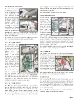
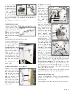
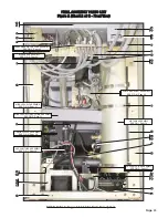
The vacuum relay (PN 800116) is the relay on the middle
shelf that has four wires connecting to it and is closest to the
air tank (Fig. 44). Remove
the female wire connectors
to the relay. Remove one
of the mounting screws
(PN 510404) with a 3/32"
Allen wrench and only
loosen the other. Slide the
relay from under the loose
screw and remove relay.
Reassemble the vacuum relay in the reverse order. Refer to
the electrical schematic for proper installation.
WASTE RELAY
The waste relay (PN 800116) is next to the vacuum relay on
the middle shelf and has six wires connecting to it (Fig. 44).
Remove the female wire connectors from the relay. Remove
one of the screws (PN 510404) with a 3/32" Allen wrench and
loosen the other screw. Slide the relay from under the loose
screw and remove relay.
Reassemble the waste relay in the reverse order. Refer to the
electrical schematic for proper installation.
Tube & Clamp
Terminal
Blocks
Power
Cord
Figure 42
Figure 43
Figure 40
Nut
Sensor
Figure 41
Sensor
Wires
Terminal Block
Power
Supply
Mtg.
Screw
3-Pin
Conn.
GND Wire
Figure 44
Waste
Relay
Vacuum
Relay

