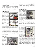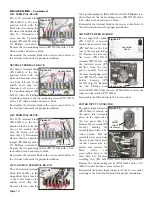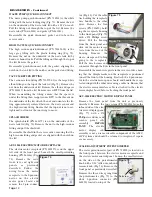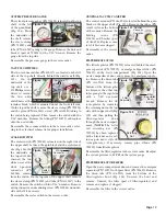
two 3-position jumpers (PN 860253) with a #2 Phillips screw-
driver. Remove the two mounting screws (PN 510720) with a
5/64" Allen wrench and remove block.
Reassemble the terminal block in the reverse order. Refer to
the electrical schematic for proper installation.
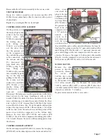
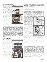
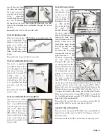
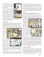
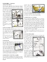
AIR INPUT FILTER HOLDER
The air input filter holder
(PN 461909) is located
behind the louvered cover
(PN 461784) on the bot-
tom of the rear panel (Fig.
49). Remove the four cap-
tive screws (PN 510715),
retainers (PN 510714), and
the louvered cover (PN
461784) from the rear
panel assembly. Unscrew
the three small primary fil-
ters (PN 730571) from the
holder housing (PN
461909) (Fig. 50). Remove
the two Phillips head
screws (PN 510191) from the cover (PN 461910) to access the
inner secondary filter (PN 730382).
Reassemble the filter holder in the reverse order.
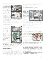
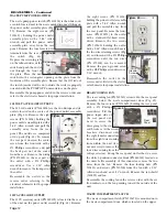
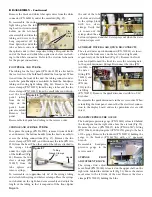
POWER INPUT CONNECTOR
The power input connector
(PN 840100) is located on
the power inlet assembly
plate, on the right side of
the rear panel (Fig. 51).
Remove the six screws (PN
510160) holding the
assembly plate with a 5/64"
Allen wrench. Pull the
assembly plate away from
the rear panel and remove
the three female wire ter-
minals that connect the
black,
white,
and
green/yellow wires to the
inlet (Fig. 52). Remove
retaining clip (PN 860269-01) and mounting hardware.
Remove the two mounting screws (PN 510016) with a 1/16"
Allen wrench, and then remove connector.
Reassemble the power input connector in the reverse order,
referring to the electrical schematic for proper installation.
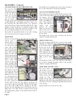
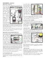
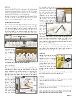
110V TERMINAL BLOCK
The 110V terminal block
(PN 860241) is the five-
position block with the
black wires located on the
left side of the middle shelf
(Fig. 45). Disconnect all
wires and the 5-position
jumper (PN 860245) with a
#2 Phillips screwdriver.
Remove the two mounting screws (PN 510720) with a 5/64"
Allen wrench and remove block.
Reassemble the terminal block in the reverse order. Refer to
the electrical schematic for proper installation.
NEUTRAL TERMINAL BLOCK
The neutral terminal block
(PN 860241) is the five-
position block with the
white and blue wires locat-
ed on the left side of the
middle shelf (Fig. 46).
Disconnect all wires and
the 5-position jumper (PN
860245) with a #2 Phillips
screwdriver. Remove the two mounting screws (PN 510720)
with a 5/64" Allen wrench and remove block.
Reassemble the terminal block in the reverse order. Refer to
the electrical schematic for proper installation.
220V TERMINAL BLOCK
The 220V terminal block
(PN 860255) is the two-
position block on the left
side of the middle shelf
with the brown and red
wires (Fig. 47). Disconnect
all wires and the 2-position
jumper (PN 860254) with a
#2 Phillips screwdriver.
Remove the two mounting screws (PN 510720) with a 5/64-
inch Allen wrench and remove block.
Reassemble the terminal block in the reverse order. Refer to
the electrical schematic for proper installation.
24V ISOLATION TERMINAL BLOCK
The 24V isolation terminal
block (PN 860243) is the
six-position block located
at the center front of the
middle shelf (Fig. 48).
Remove all wires and the
Page 10
Secondary
Filter
220V
Block
Primary
Filters
(3)
Housing Cover
Figure 47
Figure 50
DISASSEMBLY - Continued
Figure 45
110V
Block
Figure 46
Neutral Block
Jumpers
Figure 48
2-Pos Jumper
24V
Block
Louvered
Cover
Figure 49
Housing
Figure 51
Power
Input
Connector
Figure 52
Power
Input
Connector
5-Pos Jumper

