er is being replaced. Depress the retaining clips on the
inboard side of the circuit breaker and push the breaker out
through the front of the plate.
Reassemble the circuit breakers in the reverse order.
AIR TANK RELEASE VALVE
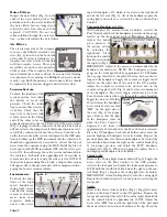
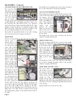
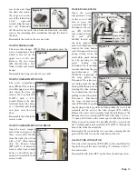
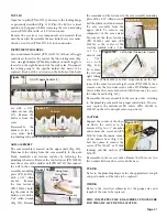
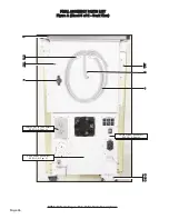
The air tank release valve (PN 730010) is the toggle valve
located on the bottom of the power outlet assembly plate, on
the rear panel (Fig. 57). Remove the eight screws (PN
510160) holding the power outlet assembly plate with a 5/64"
Allen wrench. Pull the assembly plate away from the rear
panel. Remove the sleeve clamps (PN 730095) and tubing
(PN AA-95G) from their
fittings. Use two 9/16"
open-end wrenches to
remove the toggle valve
from the assembly plate.
To reassemble the release
valve, remove the fittings
from the old valve with a
¼" open-end wrench and
attach to the new valve.
Take care not to over-
tighten the plastic fittings.
Remove the outboard nut
from the toggle valve and
turn the other nut inward
until it is close to the body
of the valve. Insert the
valve through the plate
from the inboard side with the lock washer resting against the
back side of the plate. Reattach the front nut onto the valve
from the front side of the plate and run it up the threads until
just slightly beyond the end of the valve. Use a thin 9/16"
open-end wrench to turn the nut snugly against the back side
of the plate while holding the valve body with a 9/16-inch
wrench. Ensure that the toggle is set in a horizontal working
position.
WASTE OUTLET QUICK DISCONNECT FITTING
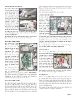
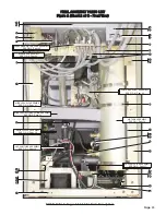
The waste outlet quick disconnect (PN 730352) is located
directly above the air tank release valve on the rear power
outlet assembly plate (Fig 57). Remove the eight screws (PN
510160) holding the power outlet assembly plate with a 5/64"
Allen wrench. Pull the assembly plate away from the rear
panel. Remove the tube (PN 730312) from the rear of the fit-
ting, then remove the quick-disconnect with a 13/16" wrench.
Reassemble the quick disconnect in the reverse order with
the release button positioned on the top side. Ensure that the
notch on the gasket and quick-disconnect are in alignment
with the notch in the power outlet assembly plate.
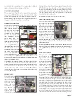
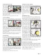
VOLTAGE SELECTOR SWITCH
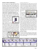
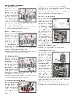
The voltage selector switch (PN 830136) is located on the
power inlet assembly plate,
above the power input con-
nector (Fig 53). Remove
the six screws (PN 510160)
holding the assembly plate
with a 5/64" Allen wrench.
Pull the assembly plate
away from the rear panel
and remove all six female
wire terminals at the switch
(Fig. 54). Remove the two
nuts (PN 510394) holding
the retaining bracket (PN
461772) with a ¼" open-
end wrench. Remove the
switch from the bracket by
depressing the retaining
clips on the switch. Remove the clear plastic voltage selector
shield (PN 461773).
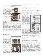
When reassembling the voltage switch, ensure that the label
(PN 420615-08) is mounted onto the switch. Then, place the
switch into the bracket with the 110V indicator towards the
top of the bracket, which is the side with the hole, rather than
the slot. Mount the bracket on the assembly plate with the
hole and the 110V indicator towards the top of the plate.
Wire the switch per the electrical schematic. With power dis-
connected, place the switch into the 110V position and check
the continuity of the wires, then place the switch into the
220V position and check the continuity again. Reassemble
the plate.
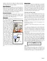
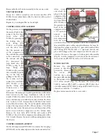
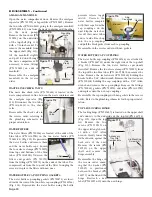
CIRCUIT BREAKERS
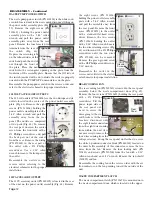
The circuit breakers are located on the power inlet assembly
plate, above the voltage
selector switch (Fig. 55).
Remove the six screws (PN
510160) holding the assem-
bly plate with a 5/64" Allen
wrench. Pull the assembly
plate away from the rear
panel assembly. Remove
the two female wire termi-
nals at each breaker that is
being replaced. Note that
the 10-amp circuit break-
ers (PN 830123) and 20-
amp breakers (PN 830122)
are attached with retaining
rings, whereas the 1-amp
breakers (PN 830138) are
not. Remove the retaining ring if a 10-amp or 20-amp break-
Page 11
Figure 55
Figure 53
Figure 54
Voltage Selector Switch
Retaining Bracket
Clear
Plastic
Shield
Label
Figure 56
Retaining
Rings
Tank Release Valve
Quick
Disconnect
Figure 57
Figure 58
Waste
Quick Disconnect
Tank Release Valve
Release
Button

