background image

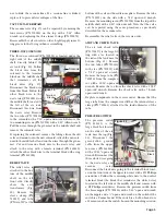
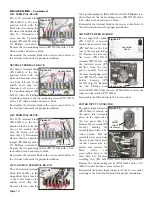
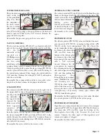
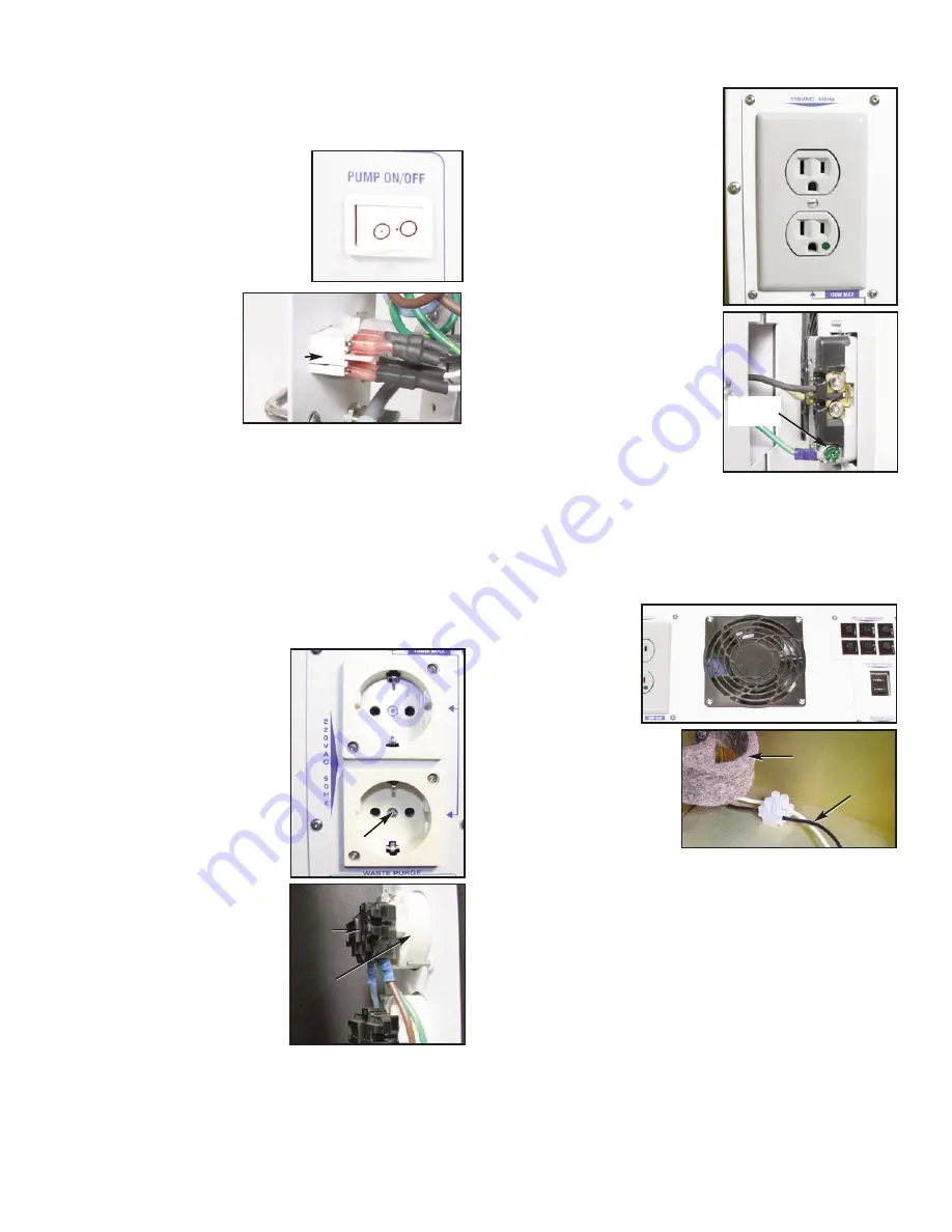
the  eight  screws  (PN  510106)

holding the power outlet assembly

plate  with  a  5/64"  Allen  wrench

and pull the assembly away from

the rear panel. Remove the front

cover  (PN  850071)  to  the  outlet

with  a  standard  flat-head  screw-

driver.  Remove  the  two  screws

(PN  510160)  holding  the  outlet

with a 5/64" Allen wrench. Locate

the two wire retaining screws (Fig.

64) and loosen with a #2 Phillips

screwdriver  until  the  two  wires

(PN  870308)  can  be  removed.

Remove  the  green  ground  screw

with a #2 Phillips screwdriver or a

5/16" wrench. 
Reassemble  the  outlet  in  the

reverse order. Refer to the electri-

cal schematic for proper installation.

REAR COOLING FAN

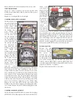
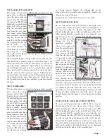
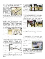
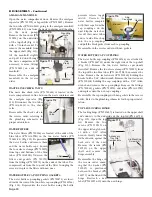
The rear cooling fan (PN 540012) is located in the rear panel

assembly,  below  the  waste  compartment  door  (Fig.  65).

Remove the four screws (PN 510691) holding the rear panel

with  a  #2  Phillips

screwdriver.  Tilt  the

power  input  side  of

the  rear  panel  out-

ward  to  access  the

wires going to the cir-

cuit breakers. At the circuit

breakers,  disconnect  only

the eight female connectors

from the eight wires coming

from  within  the  unit  (it  is

not necessary to remove the

four wires coming from the

voltage selector). Swing the rear panel out farther to access

the white 2-position connector block (PN 860244) located on

the noise baffle assembly. At this connector, remove the two

wires  from  the  fan.  Remove  the  four  locking  nuts  (PN

510411) and screws (PN 510506) from the fan with a 3/32"

Allen wrench and an 11/32" wrench. Remove the fan shield

(540009) and fan.
Reassemble the cooling fan in the reverse order with the air

flow indicator on the fan pointing toward the outside of the

unit.

WASTE COMPARTMENT LATCH

The waste compartment latch (PN 510678) is mounted onto

the waste compartment door, which is located on the upper 

WASTE PUMP POWER SWITCH

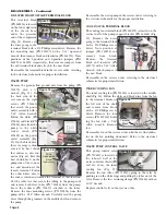
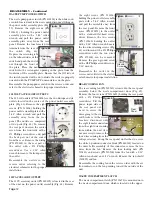
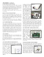
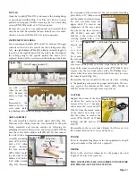
The waste pump power switch (PN 830108) is the white rock-

er switch located next to the waste quick-disconnect fitting on

the power outlet assembly plate (Fig.

59).  Remove  the  eight  screws  (PN

510160)  )  holding  the  power  outlet

assembly  plate  with  a  5/64"  Allen

wrench  and  pull  the  power  outlet

assembly  plate  away  from  the  rear

panel. Remove the four female wire

terminals from the rear of

the  switch  (Fig.  60).

Depress the retaining tabs

on the inboard sides of the

switch and push the switch

out  through  the  front  of

the  plate.  Place  the  new

switch  into  the  rectangular  opening  in  the  plate  from  the

front side of the assembly plate. Ensure that the Off side of

the switch (marked with a dot outside the circle) is properly

oriented with the PUMP OFF nomenclature on the plate.
Reassemble the pump power switch in the reverse order and

refer to the electrical schematic for proper installation.

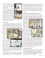
220 VOLT ACCESSORY OUTLETS

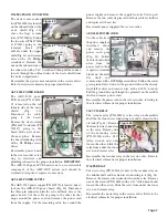
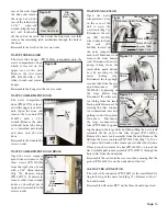
The 220 volt outlets (PN 840106) are the two European style

outlets  located  in  the  center  of  the  power  outlet  assembly

plate (Fig. 61). Remove the eight

screws  (PN  510106)  holding  the

power outlet assembly plate with a

5/64"  Allen  wrench  and  pull  the

assembly  away  from  the  rear

panel.  The  outlets  are  comprised

of two parts (Fig. 62): To remove

the rear part, unscrew the center

screw  from  the  front  side  with  a

#1  Phillips  screwdriver  and  pull

the  back  part  out  of  the  socket

from the rear. Remove the wiring

(PN  870309)  to  the  rear  part  of

the  outlet  with  a  #2  Phillips

screwdriver.  Use  a  1/16"  Allen

wrench to remove the front part of

the outlet. 
Reassemble  the  outlets  in  the

reverse  order,  referring  to  the

electrical schematic for the proper

installation.

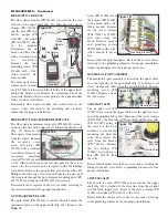
110V ACCESSORY OUTLET

The 110V accessory outlet (PN 840105) is located in the rear

of the unit, on the power outlet assembly (Fig. 63). Remove

Page 12

DISASSEMBLY - Continued

Figure 59

Retaining

Tab

Figure 60

Back

Part

Center Mtg.

Screw

Figure 61

Figure 62

Front

Part

Ground

Screw

Figure 63

Figure 64

Fan

Wires

Figure 66

Figure 65

Rear

Panel

Noise

Baffle

Assy

Summary of Contents for AMC-20CF

Page 1: ...AMC 20CF Mobile Dental System SERVICE MANUAL PARTS LIST...

Page 2: ...BLOCK 16 SYSTEM CONTROL VALVES 17 CHECK VALVE 17 35 PSI FIXED REGULATOR 17 Page i SCALER CONTROL MODULE 17 FIBER OPTICS MODULE 18 QUIN HANDPIECE BLOCK 18 MANIFOLD 4 PORT ASSEMBLY 18 AIR PILOT VALVE 1...

Page 3: ...not available in the AMC 20CF Operation and Maintenance Instruction Manual It will help you better understand the operation of the AMC 20CF Mobile Dental System thereby reducing service time A Schema...

Page 4: ...c Handpieces 2 Qty With handpiece 1 removed from its holder activate the Foot Control and check the handpiece pressure on the gauge located on the front panel marked Handpiece Pressure Adjust the hand...

Page 5: ...After the voltage selector switch is set to the proper power input sys tem voltage is controlled internally in the unit with a step down up transformer This circuit is protected by 20 Amp cir cuit br...

Page 6: ...is accessible by lifting the top lid and latching it in the upright position The power supplies compressor waste pump and miscellaneous items are accessible by removing the front and side panels Powe...

Page 7: ...30 on the side with a 7 16 open end wrench Remove the mounting screw PN 510506 from the top of the middle shelf with a 3 32 Allen wrench Note that the valve can be repaired using the same procedure as...

Page 8: ...2 Allen wrench Undo the three clamps PN 510514 around the tank with a 5 16 socket or a standard screwdriver Use a 5 32 Allen wrench to remove the two screws PN 510477 on both sides of the angle that a...

Page 9: ...ashers PN 510508 at the ends of the compressor mounting plate with a 7 16 wrench Remove the motor with mounting plates from the chassis COMPRESSOR REPLACEMENT On the old compressor PN 720024 01 remove...

Page 10: ...pump wires through the grommet in the middle shelf and remove the pump Reassemble the waste pump in the reverse order referring to the electrical schematic for the proper installation COOLING FAN TERM...

Page 11: ...cro pad Remove the two cable tie pieces from their cable tie holders and replace with new ties Reassemble power supply in the reverse order AEU 5000 POWER CORD Cut the cable tie at the power supply as...

Page 12: ...block with the black wires located on the left side of the middle shelf Fig 45 Disconnect all wires and the 5 position jumper PN 860245 with a 2 Phillips screwdriver Remove the two mounting screws PN...

Page 13: ...ase button positioned on the top side Ensure that the notch on the gasket and quick disconnect are in alignment with the notch in the power outlet assembly plate VOLTAGE SELECTOR SWITCH The voltage se...

Page 14: ...ch PN 830108 is the white rock er switch located next to the waste quick disconnect fitting on the power outlet assembly plate Fig 59 Remove the eight screws PN 510160 holding the power outlet assembl...

Page 15: ...semble with some RTV on the threads and wipe clean rear of the unit Open the door and remove the large nut on the rear of the latch with a 1 1 16 open end wrench Slip the large nut and lockwasher off...

Page 16: ...e metal locking ring Fig 73 Remove the nut on the underside of the waste tank lid with a 13 16 wrench Pull the fitting out through the top of the lid Remove the waste tube PN AA 86G and gasket PN 4610...

Page 17: ...the third tube from the right hand side underneath the pedal handpiece manifold Fig 83 Cut the two cable ties holding the two tubing splices to their fittings and remove the tube from the manifold bu...

Page 18: ...ub ing head in its instrument holder on the left hand arm assembly and trim the tubing and wires so they hang suspended off the floor Splice the end of the tube as before and attach the spliced ends t...

Page 19: ...e reverse order SYSTEM CONTROL VALVES The system control valves are on the upper shelf on the right side of the unit Fig 93 They consist of two types of valves needle type adjustment valves and toggle...

Page 20: ...Fig 99 Disconnect the sleeve clamps PN 730015 and the gray PN AA 94LG purple PN AA 94P and yellow PN AA 94TY tubes to the module Disconnect the six black and white wires with a standard jewel er s scr...

Page 21: ...ocated on the top shelf to the left of the quin block Fig 104 From the underside of the shelf remove the sleeve clamp PN 730015 and tube PN AA 94C going to the gauge Remove the nuts and bracket part o...

Page 22: ...Open the waste compartment door Remove the amalgam separator PN 730595 or bypass filter PN 730615 Remove the two tubes PN AA 86G going to the amalgam manifold PN 730596 01 one from the waste containe...

Page 23: ...SEMBLY PROCEDURE FOR THE AMC 20CF DENTAL SYSTEM TOP LID Open the top lid PN 461718 and remove the locking hinge as previously described Fig 115 Pivot the lid to a vertical position and support it whil...

Page 24: ...TE Refer to Pages 33 34 for Parts Descriptions FINAL ASSEMBLY PARTS LIST Figure A Sheet 1 of 11 FRONT PANEL ASSEMBLY SEE FIG F Page 36 ACCESSORY TRAY ASSEMBLY SEE FIG B Page 35 LEFT SIDE PANEL ASSEMBL...

Page 25: ...of 11 Front View 157 56 168 PEDAL HANDPIECE BLOCK ASSEMBLY SEE FIG Z Page 46 154 155 153 169 19 22 173 57 AIR TANK ASSEMBLY SEE FIG I Page 38 9 NOTE Refer to Pages 33 34 for Parts Descriptions 173 15...

Page 26: ...IG J Page 39 FINAL ASSEMBLY PARTS LIST Figure A Sheet 3 of 11 Right Side View 169 35 158 MIDDLE SHELF ASSEMBLY SEE FIG O Page 41 17 20 AIR TANK ASSEMBLY SEE FIG I Page 38 WASTE SHIELD ASSEMBLY SEE FIG...

Page 27: ...et 4 of 11 Left Side View 38 170 MIDDLE SHELF ASSEMBLY SEE FIG O Page 41 AEU 5000 MOUNT ASSEMBLY SEE FIG F Page 37 LEFT VENTURI ASSEMBLY SEE FIG K Page 39 54 55 168 54 161 162 141 172 153 23 10 15 18...

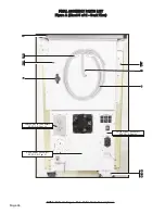
Page 28: ...Parts Descriptions 45 FINAL ASSEMBLY PARTS LIST Figure A Sheet 5 of 11 Back View REAR PANEL ASSEMBLY SEE FIG Q Page 41 POWER OUTLET ASSEMBLY SEE FIG R Page 42 POWER INLET ASSEMBLY SEE FIG S Page 43 46...

Page 29: ...SEE FIG C Page 35 MANIFOLD 4 PORT ASSEMBLY SEE FIG A A Page 46 ARMS ASSEMBLY SEE FIG A C Page 47 134 142 139 140 141 130 131 132 133 117 116 115 116 RIGHT SIDE PANEL ASSEMBLY SEE FIG D Page 36 FRONT...

Page 30: ...34 for Parts Descriptions 61 60 BULKHEAD ASSEMBLY SEE FIG X Page 45 PEDAL HANDPIECE BLOCK ASSEMBLY SEE FIG Z Page 46 SYRINGE BLOCK ASSEMBLY SEE FIG Y Page 45 129 7 21 20 174 66 80 16 38 66 58 52 18 63...

Page 31: ...EMBLY PARTS LIST Figure A Sheet 8 of 11 Right Side View NOTE Refer to Pages 33 34 for Parts Descriptions 37 29 27 28 30 153 24 25 31 32 34 PUMP BRACKET ASSEMBLY SEE FIG N Page 46 40 39 35 36 RIGHT SID...

Page 32: ...NOTE Refer to Pages 33 34 for Parts Descriptions MIDDLE SHELF ASSEMBLY SEE FIG O Page 41 44 41 42 AEU 5000 MOUNT ASSEMBLY SEE FIG F Page 37 MIDDLE SHELF ASSEMBLY SEE FIG O Page 41 163 165 170 164 9 16...

Page 33: ...LET ASSEMBLY SEE FIG R Page 42 REAR PANEL ASSEMBLY SEE FIG Q Page 41 6 49 152 34 WASTE TANK ASSEMBLY SEE FIG T Page 43 107 106 105 103 53 52 38 51 48 45 50 POWER INLET ASSEMBLY SEE FIG S Page 42 99 99...

Page 34: ...SSEMBLY SEE FIG A B Page 47 145 96 98 97 18 87 81 80 79 86 58 20 66 119 136 78 77 5 118 101 100 6 64 114 96 ARMS ASSEMBLY SEE FIG A C Page 46 137 138 80 79 92 115 116 93 94 95 70 16 83 85 34 84 47 124...

Page 35: ...730521 1 VALVE CHECK ANTI RETRACTION 730012 1 FTN ELBOW 90 10 32 X 1 16BARB WHT NYL 730011 22 VALVE TOGGLE 2W 2P GRY W O EX 730010 2 KNOB GRY PLASTIC 1 4D STYLE II 850012 5 VALVE NEEDLE CONTROL W O KN...

Page 36: ...RUBBER 730622 3 01 CLAMP 3 8 SANTOPRENE CUSHIOND PLATED 510409 1 TERM RING 8 LUG 16 14AWG BLU 860117 14 WASHER INT STAR S S 8 510420 13 NUT HEX 8 32 STNLS 510428 6 CASTER 4 POLY U POLYOLEFIN 1 2 13X1...

Page 37: ...L 510132 1 C S SOCHD BLK 1 4 20X3 4 510044 1 POST MOUNTING CLAMP CMPL 460394 08 1 ENDCAP INSERT 1 OD X 18GA BLK 510204 1 POST AUXILIARY ARM AMC 20 461889 1 ITEM PART NO QTY 9 10 11 12 13 NOT SHOWN HEX...

Page 38: ...IGHT SIDE AMC 20 461753 1 INSULATION SIDE RIGHT BOTTOM AMC 20 461921 1 INSULATOR RIGHT SIDE FILL AMC 20 461874 1 WATER BOTTLE INSERT MODULAR FRAME 461739 1 LABEL AMC 20CF 420845 1 PANEL RIGHT SIDE SIL...

Page 39: ...PCB ASSY POWER AEU 5000 COATED 330565 C 1 HOUSING LOWER AEU 5000 461797 1 C S BTNSOC STNLS 10 32X1 4 510435 2 WIRE HARNESS BOARD TO BOARD AEU 5000 KIT 875108 1 FRONT PANEL SILKSCREENED MOTOR AMC 20 4...

Page 40: ...ELBOW 90 1 4POLYX1 8MPT 730120 1 COMPRESSOR TANK ASSY AMC 20 330567 1 ITEM PART NO QTY 9 10 11 12 2 9 8 7 4 12 5 13 3 11 6 PARTS LIST Figure H Relief Valve Assembly TOP VACUUM VALVE 461853 1 C S BTNSO...

Page 41: ...OD 730351 01 1 VENTURI 0 048 DIA NOZZLE 461852 1 1 ITEM PART NO QTY 2 3 4 5 6 7 8 FTN 1 8 MPT X 3 8 BARB MODIFID 730366 08 1 BODY VENTURI AMC 20 461851 1 C S BTNSOC STNLS 8 32X1 4 510309 2 EDGE TRIM 1...

Page 42: ...LUG 3 8MPT X 5 16 HEX CSK HEAD 730637 4 COMPRESSOR OILLESS 2 HP 110V THOMAS MOD 720024 01 1 FTN INSERT 1 2 OD BRASS INSERT INTO TUBE 730261 1 ITEM PART NO QTY 9 10 11 1 4 7 5 6 11 9 12 2 3 10 12 PARTS...

Page 43: ...60243 1 C S BTNSOC STNLS 6 32X5 8 510720 8 CONN JUMPER 7 16 CNTR 2 POS 860254 1 CONN TERMINAL BLOCK 7 16 CNTR 20A 2 POS 860255 1 CONN JUMPER 7 16 CNTR 5 POS 860245 2 TERM BLOCK 7 16 CNTR 20A 5 POS 860...

Page 44: ...ure R Power Outlet Assy PLATE WALL DUPLEX RECEP 1 GANG GREY 850071 1 PWR OUTLET DUPLEX 15A HOSP GRADE GREY 840105 1 C S BTNSOC STNLS 6 32X3 8 510160 2 PWR OUTLET EURO SCHUKO SNGL RECP CEE 7 840106 2 C...

Page 45: ...ART NO QTY 9 10 11 12 2 4 7 8 3 5 6 12 9 13 PARTS LIST Figure T Waste Tank Assembly SENSOR ASSY WASTE TANK AMC 20 330555 1 GASKET AEU 425 AIR BOTTLE 461011 2 STRAIN RELIEF NUT 3 8 BLK 840015 1 TUBE WA...

Page 46: ...ER AMC 20 461755 1 ITEM PART NO QTY 9 10 1 9 8 4 7 3 2 5 6 10 PARTS LIST Figure U Noise Baffle Assembly RIVET BLIND AL AL 1 8D3 16 1 4 510170 16 WASHER BLIND RIVET 1 8 510198 12 NUT NYLOC 4 40 STNLS H...

Page 47: ...ANEL AMC 20 461699 1 ITEM PART NO QTY 9 10 11 12 4 7 10 12 11 5 6 2 1 2 1 3 8 9 8 PEDAL HANDPIECE BLOCK ASSEMBLY SEE FIG Z Page 46 SYRINGE BLOCK ASSEMBLY SEE FIG Y Page 45 PARTS LIST Figure W Waste Sh...

Page 48: ...2 2 3 4 7 6 2 PARTS LIST Figure Y Syringe Block Assembly FTN BARB 10 32 X 1 16 PLATED 730062 4 GASKET NYLON 10 730074 4 1 ITEM PART NO QTY 2 3 BLOCK INTERFACE SYRINGE AMC 20 461775 1 ITEM PART NO QTY...

Page 49: ...ATING SPINDLE TOP AMC 20 461696 1 WASHER WAVE DISC 2 740 ID X 3 519 OD 510673 2 ARM ROTATING ACETAL WASHER AMC 20 461698 4 1 ITEM PART NO QTY 2 3 4 5 6 7 8 9 10 11 12 13 14 15 16 COVER ARM TUBING LEFT...

Page 50: ...TION AND MAINTENANCE Excessive dust and debris may cause a drastic decrease in optical output In the event that the light requires cleaning first try a gentle swabbing using a lint free swab If need e...

Page 51: ...autoclavable Disinfect and clean the Cover and Tips before autoclaving Autoclave at a maximum temperature of 135 C 275 F for 10 minutes or 120 C 248 F for 20 minutes Wipe off the Scaler Handpiece and...

Page 52: ...ce is open Check that the toggle is in the On position Check that the flow control valve is open Check to see if the amalgam separator is clogged by replacing it with the by pass filter Waste tank is...

Page 53: ...ant switch ON Operate handpiece until such time that coolant water sprays from handpiece outlet in a uniform spray Adjust water coolant flow valve from minimum to maximum flow to verify proper functio...

Page 54: ...Bottle Select Toggle Footswitch On Off Switch Mains Temperature Limitation Manufacturer Humidity Limitation Atmospheric Pressure Limitation Type BF Equipment Authorized European Representative Motor...

Page 55: ...0 15 liter min Waste Tank Capacity 1 08 gal 4 08 liters Noise Level 59 dBA 3 4 1 meter 20CF Cart Duty Cycle Continuous Compressor Duty Cycle 33 5 minutes ON 10 minutes OFF when operating at 50 Hz Ele...

Page 56: ...ged defect under warranty the purchaser is to notify Aseptico s Customer Service Department promptly Customer Service will provide instructions usually directing that the product be returned for servi...

Reviews: