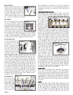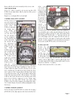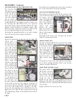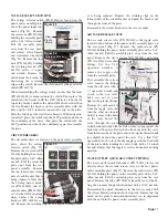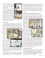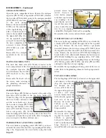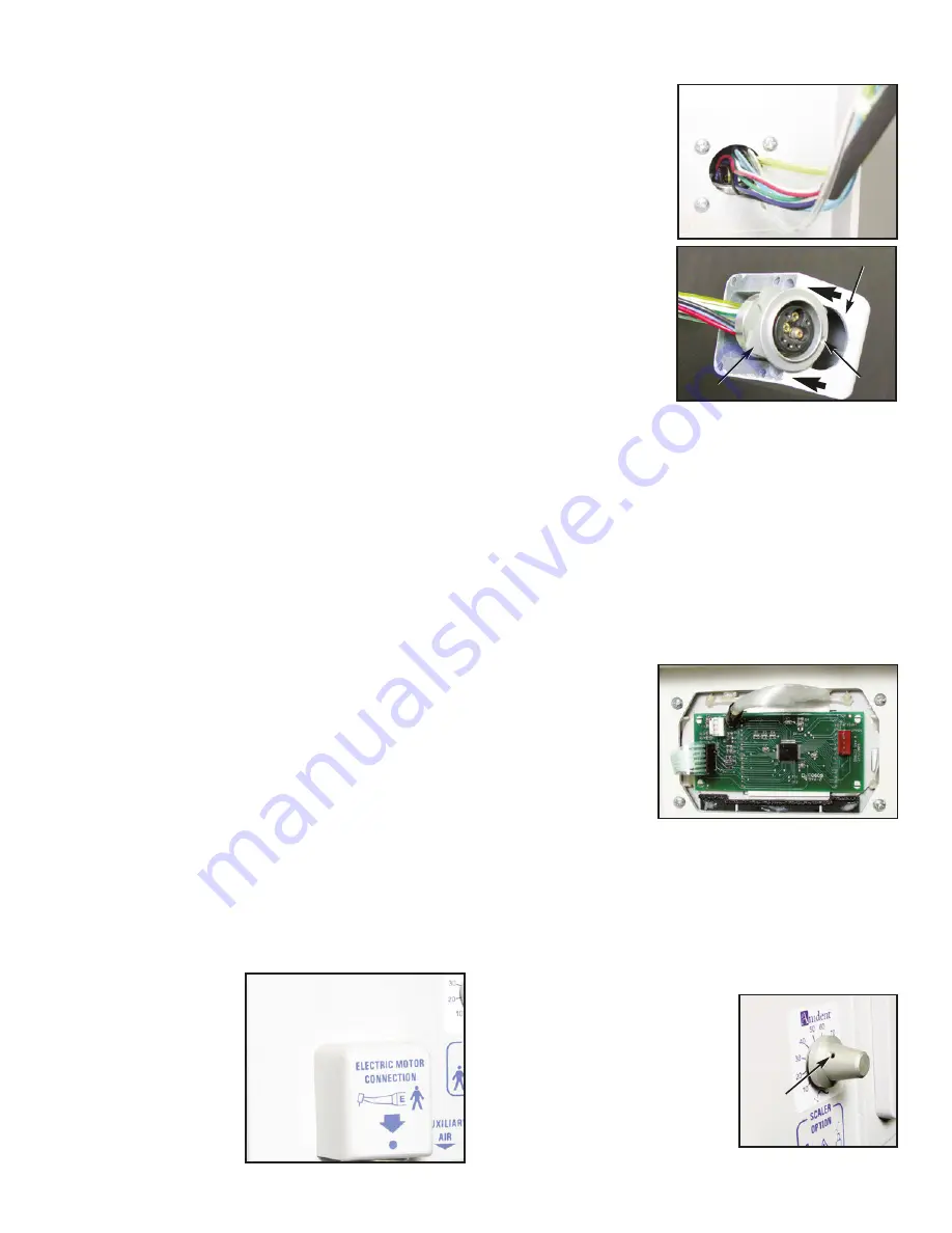
tor (Fig. 42). Cut the cable
ties holding the receptacle
wire bundle to the other
wires. Remove the four
screws (PN 510650) hold-
ing the receptacle housing
to the front panel (Fig. 75)
with a #2 Phillips screw-
driver. Pull the housing
from the front panel and
slide out the motor recep-
tacle from the rear of the
housing. Remove the
sleeve clamps and tubing
going to the receptacle.
Pull the wire harness and
connector through the hole in the front panel .
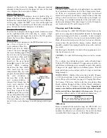
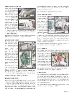
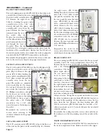
Reassemble the motor receptacle in the reverse order, ensur-
ing that the dimple marker on the receptacle is positioned
toward the front of the housing. Reattach the 8-pin connec-
tor to the electric motor power board and bundle the recep-
tacle wiring with the other wires using a cable tie. Ensure that
the electric motor interface cable is attached to the electric
motor display board before attaching the front panel.
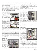
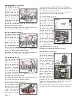
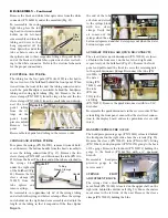
AEU-5000 ELECTRIC MOTOR DISPLAY PANEL
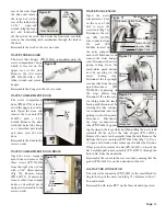
Remove the front panel from the unit as previously
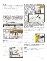
described. Remove the four screws (PN 510650) from the
inboard side of the elec-
tric motor display panel
(Fig. 77) with a #2
Phillips screwdriver and
remove panel sub-
assembly.
IMPOR-
TANT:
The electric
motor display sub-
assembly is not a user-serviceable component of the AMC-
20CF system and should be returned to Aseptico if repairs
are necessary.
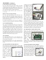
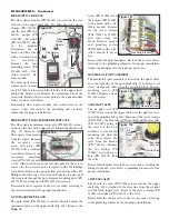
SCALER ADJUSTMENT POTENTIOMETER
The scaler potentiometer (part of PN 730500) is located on
the front panel, between the electric motor receptacle and
the electric motor control panel. Loosen the small setscrew
on the side of the potentiometer
knob with a 1/32" Allen wrench and
remove knob (Fig. 78). Remove the
front panel as previously described.
Remove the three wires going from
the potentiometer (Fig. 79) to the
white 3-position connector (PN
860250) located on top of the
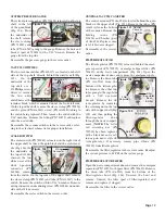
WASTE PUMP QUICK DISCONNECT
The waste pump quick-disconnect (PN 730516) is the white
fitting with the metal locking ring (Fig. 73). Remove the nut
on the underside of the waste tank lid with a 13/16" wrench.
Pull the fitting out through the top of the lid. Remove the
waste tube (PN AA-86G) and gasket (PN 461011).
Reassemble the quick disconnect, gasket, and tube in the
reverse order.
HIGH VACUUM QUICK DISCONNECT
The high vacuum quick-disconnect (PN 730354-08) is the
large gray fitting with the plastic locking ring (Fig. 73).
Remove the nut on the underside of the waste tank lid by
hand or channel locks. Pull the fitting out through the top of
the lid. Remove the gasket.
Reassemble quick-disconnect with the gasket, aligning the
notch on the tank lid to the notches on the gasket and fitting.
VACUUM RETURN FITTING
The vacuum return fitting (PN 730599-01) is the large white
elbow fitting on the top of the tank lid (Fig. 73). Remove the
nut from the underside of lid. Remove the elbow and spacer
(PN 461819) from the lid. Remove excess RTV from the lid.
When reassembling the fitting, ensure that the spacer is
under the fitting then reapply some RTV to the threads on
the underside of the lid. Attach the nut and orientate the fit-
ting approximately centered between the waste sensor and
the high vacuum fitting. Ensure that the top nut is not over-
tightened to allow for the inner ring to move.
SPLASH SHIELD
The splash shield (PN 461879) is on the underside of the
waste tank lid (Fig. 72). Remove the nut to the high-vacuum
fitting and pull the shield off.
Reassemble the shield in the reverse order, ensuring that the
high vacuum fitting and gasket are aligned with the notch on
the lid.
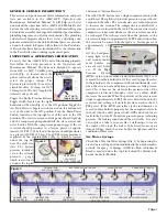
AEU-5000 ELECTRIC MOTOR RECEPTACLE
The electric motor receptacle (PN 330557) is on the upper
left side of the front panel, beneath the small protruding
housing (PN 461886) (Fig.
74). Remove the cart's
front, left, and right side
panels as previously
described. Follow the
wiring from the motor
receptacle to the 8-pin con-
nector on the electric
motor power board and
remove the 8-pin connec-
Page 14
DISASSEMBLY - Continued
Figure 74
Figure 75
Figure 76
Housing
Receptacle
Figure 77
Dimple
Figure 78
Setscrew


