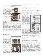
line. Trim the ground wire to the proper length and crimp on
a #8 ring terminal. Wrap the cable tie around the scaler cord,
just above the bulkhead grommet. Ensure that the tie is not
over-tightened and does not restrict the flow of water. Attach
the yellow anchor line to the hold-down screw. Attach the
white and black wires from the wand to the matching colored
wires on the two-position terminal block. Check to ensure
that scaler water flow is appropriate before reattaching the
front panel.
PNEUMATIC HANDPIECE FIBER-OPTIC TUBING
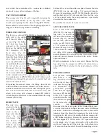
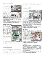
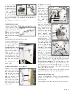
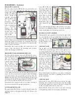
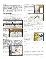
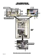
The two sets of gray tubing (PN AA-19A-04T6) carrying the
fiber-optic wires for the two pneumatic handpiece adapters
are located on the bulkhead, behind the front panel. When
viewed from the front of the unit, the two tubing sets are
positioned under the right-hand side of the pedal/handpiece
manifold (Fig. 83).
Cut the four cable
ties holding the
front tubing splices
to their fittings and
disconnect splices.
Remove the four
sleeve clamps (PN
730015) from the
other four tubing
splices and disconnect the
splices from their fittings.
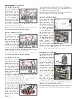
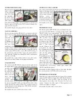
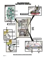
At the 4-position white
connector (PN 860250)
located on the bottom side
of the manifold (Fig. 84),
remove the black and
white fiber-optic wires
from the connector.
To reassemble the pneumatic handpiece tubing, place the two
handpiece adapters in their holders on the left-hand arm
assembly and trim the supply hoses to their proper length so
they are suspended off the floor. Splice the ends of the two
tubes as before and attach the spliced ends to their appro-pri-
ate fittings on the pedal/handpiece manifold with cable ties
and/or sleeve clamps. Strip and tin the ends of the black and
white fiber-optic wires before reattaching them to the white
connector on the bottom side of the bulkhead. Refer to elec-
trical schematic for proper installation.
CURING LIGHT TUBING
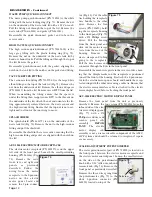
The curing light tubing (PN 730625) is located on the bulk-
head, behind the front panel. When viewed from the front of
the unit, the tubing is the third tube from the right-hand side,
underneath the pedal/handpiece manifold (Fig. 83). Cut the
two cable ties holding the two tubing splices to their fittings
and remove the tube from the manifold.
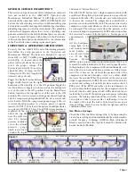
bulkhead. Remove the nut on the
outboard side of the front panel with
a ½" socket. From the inboard side,
remove potentiometer through the
hole in the panel.
Reassemble the scaler poten-tiome-
ter in the reverse order with the lock
washer positioned against the
inboard side of the front panel and
the alignment pin on the poten-
tiometer keyed into the hole in the
cover. At the white connector on the
bulkhead, color-match the three
potentiometer wires to the brown,
red, and orange wires in the connec-
tor. Ensure that the electric motor
interface cable is attached to the electric motor display board
before attaching the front panel.
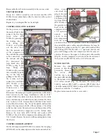
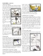
SCALER WAND
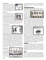
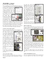
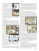
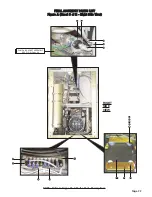
The scaler wand (part of PN 730500) is attached through the
bulkhead, behind the front panel. Remove the front cover as
previously described and pull cover forward to access the top
of the bulkhead. Remove the ground wire mounting screw
(PN 510404) from the side panel on the bulkhead (Fig. 81)
with a 3/32" Allen wrench. Remove the black and white scaler
wires going to
the white 2-
position con-
nector block
(PN 860244)
on the bulk-
head. Cut the
cable
tie
around the
scaler cord,
located just
above the grommet.
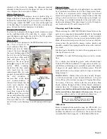
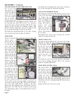
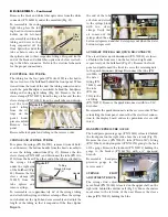
Remove the scaler tube
anchor line from the
hold-down screw (PN
510435) with a 5/32"
Allen wrench. On the
upper shelf, disconnect
the clear tube going
from the scaler wand tube to the scaler coolant valve, at the
valve (the fourth valve from the right when viewed from the
inboard side - Fig. 82). From the bottom of the bulkhead,
remove the scaler wand cord down through the grommet.
Remove scaler wand.
Reassemble the scaler wand in the reverse order, adjusting
the length of the wand cord to hang suspended off the floor
and then trimming the excess cord sleeve clamp and/or water
Page 15
Figure 79
Figure 80
Bulkhead
Ground
Wire
Figure 81
Figure 82
Scaler Coolant Tube
Connector
Block
Anchor
Line
Cable
Tie
Hold-Down Screw
Pedal/Handpiece Manifold
Pneumatic Handpiece Tubing
Figure 83
Figure 84
Fiber Optic
Wires
Curing
Light
Tubing

