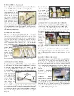
the end of the tube
as before and attach
to the syringe block
with two sleeve
clamps. Verify that
air comes out the
syringe when the air
button is depressed and that water sprays out when the water
button is depressed.
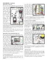
AUXILIARY WATER & AIR QUICK DISCONNECTS
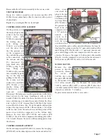
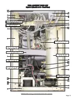
The air and water quick disconnects (PN 730033) are locat-
ed behind the front cover, on the far left and right ends,
respec-tively, of the bulkhead (Fig. 89). Remove the front
panel and pull toward the front to access the retaining nuts
to the quick disconnect fittings. Disconnect the tube (PN
AA-94B) to
the water
fitting (PN
730011) and
the tube
(PN AA-
95G) to the
air fitting
(PN 730073). Remove the quick disconnects with two 9/16"
wrenches.
Reassemble the quick disconnects in the reverse order. When
reinstalling the front panel, ensure that the electrical connec-
tion to the display board and scaler potentiometer are still
intact.
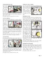
HANDPIECE PRESSURE GAUGE
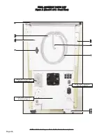
The handpiece pressure gauge (PN 730132) is located behind
the front panel on the right side, above the air tank (Fig. 90).
Remove the sleeve (PN 730015), tube (PN AA-94C), fitting
(PN 730062), and nylon gasket (PN 730074) going to the back
of the gauge. Remove the locknuts (PN 510394) holding the
gauge to the bracket (PN 461741) with a ¼" open-end
wrench.
Reassemble handpiece
pressure gauge in the
reverse order.
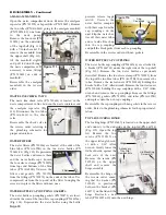
SYRINGE
FLOW
ADJUSTMENT BLOCK
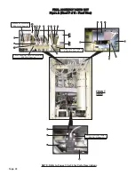
The syringe flow adjust-
ment block (PN 730022) is located on the upper shelf, on the
right side, behind the divider wall (Fig. 91). Move the instru-
ment arms to the left side of the unit. Remove the sleeve
clamps (PN 730015) holding the blue
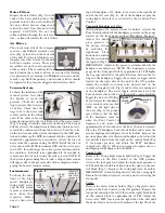
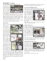
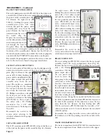
Remove the black and white fiber optic wires from the white
connector (PN 860244) under the manifold (Fig. 85).
To reassemble the curing
light tube, place the tub-
ing head in its instrument
holder on the left-hand
arm assembly and trim the
tubing and wires so they
hang suspended off the
floor. Splice the end of the
tube as before and attach
the spliced ends to their respective fittings. Strip and tin the
end of the black and white fiber-optic wires before reattach-
ing to the white connector. Refer to the electrical schematic
for the proper connections.
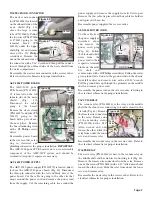
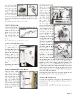
FOOT PEDAL AND TUBING
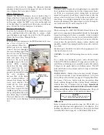
The tubing for the foot pedal (PN AA-43W) is attached to
the rear center of the bulkhead behind the front panel. When
viewed from the front of the unit, the tubing connects under-
neath the pedal/handpiece manifold, behind the handpiece
tubing and curing light tubing (Fig. 86). Remove the two
sleeve clamps (PN 730095) from the large tubes and the two
sleeve clamps (PN 730015) from the small tubes and discon-
nect the foot-
pedal tubing
from the fit-
tings on the
pedal/ hand-
piece manifold.
Remove foot
pedal.
Reassemble foot pedal and tubing in the reverse order.
SYRINGE AND SYRINGE TUBING
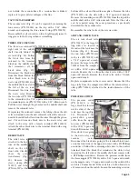
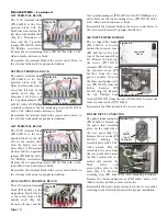
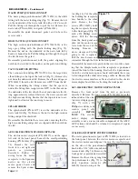
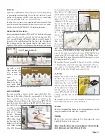
To replace the syringe (PN TA-90D), remove it from its hold-
er and unscrew the bottom handle from the head assembly to
access the tubing connections (Fig. 87). Remove the two
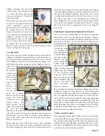
sleeve clamps (PN 730015) and disconnect the tube (PN AA-
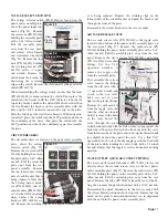
85G) from the head. The other end of the tube is attached to
the syringe block
under the right side
of the bulkhead (Fig.
88). Remove the two
sleeve clamps (PN
730015) from the
tube splices and
remove syringe.
To reassemble, cut approximately 66" of the syringe tubing
and attach to the syringe with sleeve clamps. Place the syringe
in its holder on the right-hand arm assembly and adjust the
length of the tubing so that it suspends off the floor. Splice
Page 16
DISASSEMBLY - Continued
Figure 85
Fiber
Optic
Wires
Figure 86
Foot Pedal Tubing
Figure 87
Tubing
Sleeve Clamps
(2)
Handle
Figure 88
Syringe
Block
Syringe
Tubing
Water
Quick
Disconnect
Air
Quick
Disconnect
Figure 89
Figure 90
Bracket
Gauge

