closed and attach the knob with the setscrew, allowing some
clearance between the knob and body. Ensure that the knob
does not bottom out against the valve.
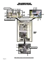
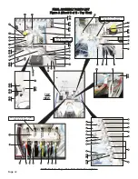
CHECK VALVE
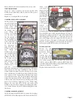
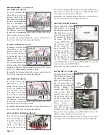
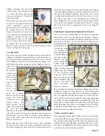
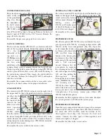
The check valve (PN 730012) is located on the upper shelf, in
line between the bottle-select toggle and the 4-port manifold
(Fig. 95). Remove the
sleeve clamps (PN
730015) and tubes (PN
AA-94B) and remove
the valve.
Reinstall check valve
in the reverse order .
Ensure that the flow
direction is toward the
manifold.
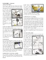
35 PSI FIXED REGULATOR
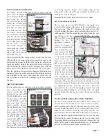
This regulator (PN 730521) is located on the upper shelf, in
line between the manifold and bottle-pressure On/Off toggle
(Fig. 96). Remove the
sleeve clamps (PN
730015) and tubing
(PN AA-94C).
Replace regulator,
ensuring that the air
direction arrow is
pointing towards the
toggle valve.
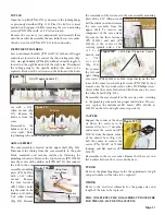
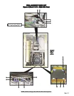
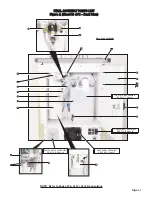
SCALER CONTROL MODULE
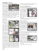
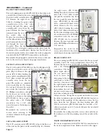
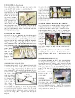
The scaler control module (PN 730500) is located on the
right side of the upper
shelf, behind the
divider wall (Fig. 97).
Remove the two
screws (PN 510530)
from under the chassis
with a #1 Phillips
screwdriver. Lift the module and
slide back the top cover on the
module to remove the electrical
connector to the module (Fig.
98).
Reassemble the control module
in the reverse order.
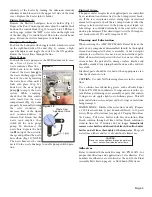
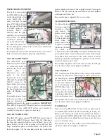
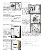
(PN AA-94B) and clear
(PN AA-94C) tubes to
the fittings, then remove
the tubes. Remove the
flow adjustment block
mounting screw (PN
510404) on the out-
board side of the divider
wall with a 3/32” Allen
wrench (Fig. 92). Pull
the adjustment block up
and remove the two blue and clear tubes to the block.
Replace label (PN 420748-07) if necessary.
Reassemble the syringe flow adjustment block in the reverse
order.
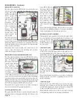
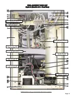
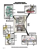
SYSTEM CONTROL VALVES
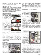
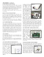
The system control valves are on the upper shelf, on the right
side of the unit (Fig. 93). They consist of two types of valves:
needle-type
adjustment
valves and toggle-type on/off
valves (Fig. 94). Remove the
tubing to all valves being
replaced. Remove all elbow
fittings (PN 730011), straight
fittings (PN 730062), and
nylon gaskets (PN 730074)
from valve bodies if neces-
sary. To replace a needle
valve, first loosen the
setscrew on the adjustment
knob (PN 850012) with a
1/16" Allen wrench, then
remove knob. For all
valves and toggles, use a
9/16" open-end wrench
to remove outboard nut
from the chassis wall.
Pull needle and toggle
valve bodies through
the holes in the chassis wall, from the inboard side.
To reassemble a needle or toggle valve, first remove the
mounting nut from the outboard end of the valve and turn
the inboard nut toward the body of the valve slightly. Then,
place the valve through the chassis hole from the inboard side
with the lock washer placed against the inboard side of the
chassis wall. Install the mounting nut onto the outboard end
of the valve and run the nut up just a couple threads from the
outboard end. Tighten the valve in place by holding the body
and tightening the inboard nut against the chassis wall with a
thin 9/16" open-end wrench. On toggle valves, ensure that the
toggle is in its proper orientation with the nomenclature on
the side panel. On needle valves, adjust the needle to fully
Page 17
Check Valve
Figure 93
Figure 95
Figure 91
Adjustment
Block
Figure 92
Figure 94
Needle Valve
Toggle Valve
Setscrew
FLOW
Manifold
Regulator
Figure 96
Flow Direction
Arrow
Bottle Pressure
On/Off Toggle
Figure 97
Scaler Control
Module
Figure 98
Electrical
Connector
Block Mounting
Screw

