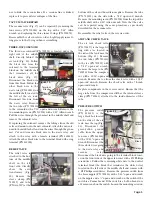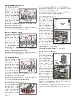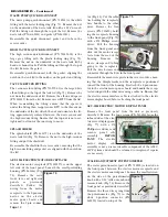
screw (PN 510404) from
the bracket (PN 510256)
to the block with a 1/8"
Allen wrench. Remove
all the sleeve clamps
(PNs 730015 & 730095)
and tubes from the
block. Remove bracket
and mounting screws
(PN 510404) with a 3/32"
Allen wrench if neces-
sary.
Reassemble the quin handpiece block in the reverse order,
referring to the plumbing schematic for proper installation.
Adjust the handpieces to their proper pressures.
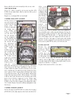
MANIFOLD 4-PORT ASSEMBLY
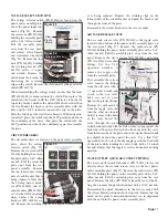
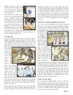
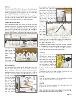
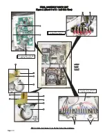
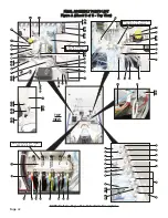
The manifold 4-port assembly is located on the upper shelf,
near the right side of the quin block (Fig. 102). Remove all
sleeve clamps and tubes from the assembly block. Remove
mounting screw (PN
510423). Replace assem-
bly if necessary.
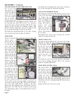
AIR PILOT VALVE
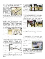
The air pilot valve (PN
730019) is located on the upper shelf, near the right rear cor-
ner of the quin block (Fig. 103). Disconnect the sleeve clamps
(PN 730015), the blue tubes (PN AA-94B) and the clear tube
(PN AA-94C) going to
the valve. Use two 9/16"
wrenches to remove the
mounting nut from the
valve then remove the
valve from the bracket
(PN 730245). Remove
the two fittings (PN
730062) and nylon gas-
kets (PN 730074) from
the valve.
Reassemble the pilot valve in the reverse order, attaching the
fittings to the new valve. Refer to plumbing schematic for the
proper installation.
SHUTTLE VALVE
The shuttle tee valve (PN 730016) is located on the upper
shelf (Fig. 103), attached to the clear line from the air pilot
and the flush toggle valve. Remove the sleeve clamps (PN
730015) and tubes (PN AA94C) at the valve.
Reassemble the shuttle valve in the reverse order, referring
to the plumbing schematic for the proper installation.
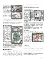
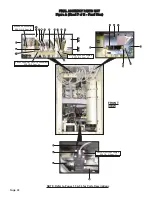
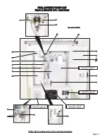
FIBER OPTICS MODULE
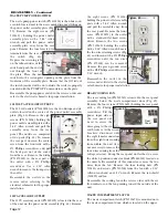
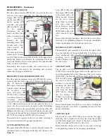
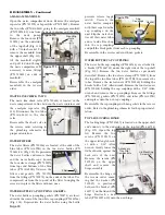
The fiber optics module (PN 730623) is located on the rear
left side of the upper shelf (Fig. 99). Disconnect the sleeve
clamps (PN 730015)
and the gray (PN AA-
94LG), purple (PN
AA-94P), and yellow
(PN AA-94TY) tubes
to
the
module.
Disconnect the six
black and white wires
with a standard jewel-
er's
screwdriver.
Remove the four
mounting screws (PN
510160) with a 5/64"
Allen wrench. Re-
move module.
The fiber optic trans-
former (part of mod-
ule, PN 730623) is located on the left side of the upper shelf,
behind the divider wall. Remove the transformer from the
receptacle. Remove the two wires going to the optics module
with a jeweler’s screwdriver.
Reassemble fiber optics module and transformer in the
reverse order, referring to the plumbing and electrical
schematics for proper installation.
FIBER OPTIC TRANSFORMER RECEPTACLE
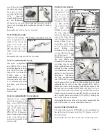
The fiber optic transformer receptacle (PN 840105) is locat-
ed on the left side of the upper shelf, behind the divider wall
(Fig. 99). Remove the
fiber-optics trans-former
from the socket. Remove
the receptacle cover
screw and plate (PN
850071) with a standard
screwdriver. Remove the
receptacle
mounting
screws (PN 510160) with
a 5/64" Allen wrench. Open the left-side panel of the cart to
remove the two wires from the receptacle with a #2 Phillips
screwdriver. Remove the green/yellow ground wire with a #2
Phillips screwdriver or a 5/16" wrench. From the top side, pull
the receptacle through the hole. Remove mounting plate (PN
461771-01) and four nuts (PN 510395) if necessary.
Reassemble the receptacle in the reverse order, referring to
the electrical schematic for proper installation.
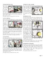
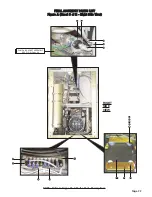
QUIN HANDPIECE BLOCK
The quin block (PN 730621) is located directly behind the
instrument arms on the upper shelf (Fig. 101). Remove the
Page 18
Mounting Bracket
Figure 101
DISASSEMBLY - Continued
Figure 99
Fiber
Optics
Module
Transformer
Tubes
Black Wires
Mounting Plate
Receptacle
Figure 100
Transformer
Receptacle
Mounting Screw
Figure 102
Mounting
Bracket
Figure 103
Air
Pilot
Valve
Shuttle Valve


