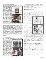
pressure release toggle
switch. Unscrew the
water bottles, complete
with their caps, from the
cap couplings on the
unit. Slip the water bot-
tles off their water tubes
and set aside. Reach up
into the cap couplings
and pull the black gasket from each cap coupling.
Reassemble in the reverse order with new gaskets.
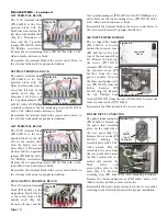
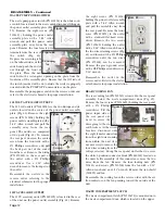
WATER BOTTLE CAP COUPLINGS
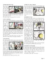
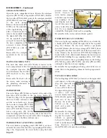
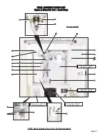
The water bottle cap couplings (PN 461566) are attached to
a bracket (PN 461733) under the right side of the top shelf
(Fig. 114). Remove the two water bottles as previously
described. Remove the two sleeve clamps (PN 730095) from
the top of the two blue tubes (PN AA-95B), then remove the
tubes. Remove the six fasteners (PN 510160) holding the
bracket with a 5/64" Allen wrench. Remove the four fasteners
(PN 510404) holding the cap couplings with a 3/32" Allen
wrench and remove the cap couplings. Remove the fittings
(PN 730062), gaskets (PN 730074), and tubes (PN AA-95B)
and replace onto the new cap couplings.
Reassemble the cap couplings with new gaskets in the reverse
order. Refer to the plumbing schematic for the proper instal-
lation.
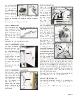
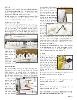
TOP LID LOCKING HINGE
The locking hinge (PN 510687) is located on the upper shelf
and connects to the underside of the top lid (PN 461718)
(Fig. 115). Open the top
lid. Remove the two
screws (PN 510545) on
the upper lid angle brack-
et with a 3/32" Allen
wrench. Gently lower the
lid backwards, against the
back side of the unit.
Remove the screws (PN
510533) on the upper
shelf and remove the
hinge assembly.
Reassemble the hinge in
the reverse order, ensur-
ing that the washer (PN
510019) is positioned
between the bracket (PN
461875) on the lid and the
hinge. Reattach a new
label (PN 420556-10) onto the new hinge.
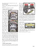
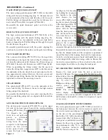
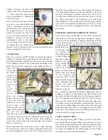
AMALGAM MANIFOLD
Open the waste compartment door. Remove the amalgam
separator (PN 730595) or bypass filter (PN 730615). Remove
the two tubes (PN AA-86G) going to the amalgam manifold
(PN 730596-01): one from the waste container and the other
to the waste pump.
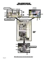
Remove the four nuts (PN
510296) on the underside
of the top shelf (Fig. 110)
with a 7/16-inch socket. To
remove the manifold from
the upper shelf (Fig. 111),
tilt the manifold slightly
and pull it down through
the waste compartment. If
necessary, remove fittings
(PN 730613) on ends of
manifold.
Reassemble the amalgam
manifold in the reverse
order.
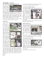
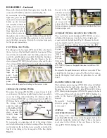
WASTE LINE CHECK VALV
E
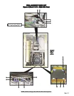
The waste line check valve (PN 730634) is located in the
waste compartment, in line between the waste container and
the amalgam separator (Fig.
112). Disconnect the two tubes
(PN AA-86G) to the check
valve.
Reassemble the check valve in
the reverse order, referring to
the plumbing schematic for
proper orientation.
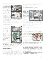
WATER FILTERS
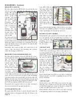
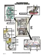
The water filters (PN 730326) are located at the ends of the
blue tubes (PN AA-95B) in the two water bottles (PN
730631-01) (Fig. 113). Depressurize
the water bottles and remove them
and the water bottle caps. Loosen
the four sleeve clamps (PN 730095)
from tops and bottoms of the blue
tubes (PN AA-95B). Unscrew the
filters and gaskets (PN 730074)
from the fittings (PN 730073) on the ends of the tubes. Use
compressed air from the top end of the filter to unplug the
screen, or replace the filters with new ones.
WATER BOTTLE CAP COUPLING GASKETS
The water bottle cap coupling gaskets (PN 730473) are locat-
ed inside the rims of the two white cap couplings (PN 461566)
(Fig. 114). Depressurize the water bottles using the bottle
Page 20
DISASSEMBLY - Continued
Manifold
Figure 110
Figure 111
(Top
View)
Mounting
Nuts
(4)
Manifold
Figure 112
Check
Valve
Figure 113
Filter
Figure 114
Gasket
Cap
Couplings
Bracket
Figure 115
Hinge
Lid Mounting
Screws (4)
Accessory
Tray Mtg.
Components


