Page 2
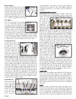
Water Filters
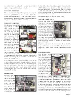
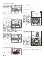
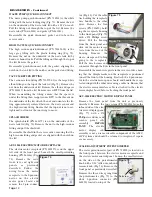
Inspect the water filters (Fig. 5) on the
ends of the water pick-up tubes that
protrude into the two water bottles. If
the water filters become clogged and
restrict the water flow, they need to be
replaced. CAUTION: Do not run
saline solutions through the water sys-
tem -- saline will corrode the water filters.
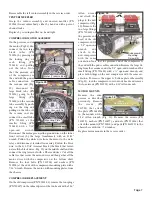
Air Filters
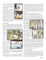
The air pressure side of the compres-
sor uses a dual-filtered air intake can-
ister (Fig. 6) located on the back side
of the unit. It is located behind a rec-
tangular cover that attaches to the unit
with four captive screws. Three pri-
mary filters are on the outer perimeter
of the canister. The secondary filter is
located inside the canister and can be accessed for cleaning
or replacement by removing two Phillips head screws on the
canister cap. Both the primary and secondary filters should
be replaced if they become clogged and restrict air flow.
Vacuum System
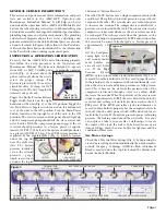
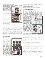
To check the function of the
vacuum system, first allow
the System to reach full
pressure. Check the solids
trap to ensure that it is clear
of debris. Check that the
large tube to the waste tank
is fully seated in the fitting
and all the other tubes are
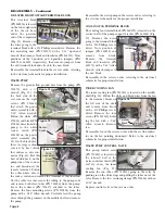
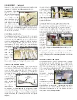
properly connected to the tank. Ensure that the waste sensor
(Fig. 7) is plugged into the connector on the unit. The System
will not activate the compressor if this connection is not acti-
vated. Fill a container with one liter of water. Turn the valve
on the low vacuum saliva ejector instrument to the OFF posi-
tion and submerge the HVE instrument into the container. It
should take approximately 6 seconds to extract the liter of
water from the container using the HVE. Refill the liter of
water and turn the HVE instrument OFF and the saliva ejec-
tor to ON, then submerge the saliva ejector instrument into
the container. It should take approximately 42 seconds to
remove one liter of water using the saliva ejector. NOTE: If
the System is pressurizing the air tank, a drop in this vacuum
will appear due to the pressure side of the compressor disen-
gaging the booster vacuum venturi.
Instruments
To check the func-
tions of the high-
speed handpieces,
curing light, scaler,
and electric motor,
remove each instru-
ment from their
respective holders
one at a time, start-
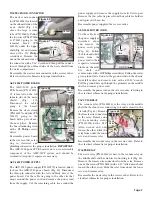
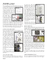
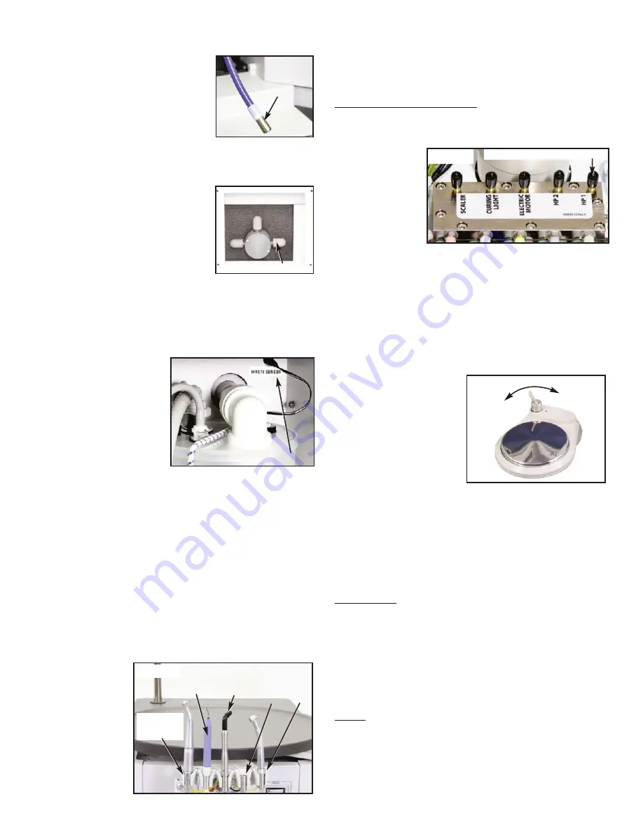
ing with handpiece #1, which is located on the right-hand
end of the left arm (Fig. 8). All of the handpieces plus the
curing light and scaler are activated by the air-driven Foot
Control.
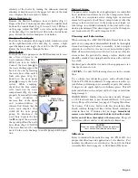
Pneumatic Handpieces (2 Qty):
With handpiece #1 removed from its holder, activate the
Foot Control and check the handpiece pressure on the gauge
located on the front panel marked "Handpiece Pressure".
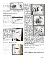
Adjust the hand-
piece pressure to
the proper setting
by adjusting the
right-hand black
knob on the control
block located under
the top Lid (Fig. 9).
IMPORTANT: Adjust to the pressure recommended by the
handpiece manufacturer. NOTE: The handpiece pressure
gauge on the front panel will be approximately 3 PSI higher
than a gauge installed at the end of the line, between the fit-
ting and the handpiece. Toggle the coolant air toggle switch
located on the right side of the unit to the ON position.
Adjust the coolant air control valve (located next to the
coolant air toggle switch - Fig. 3) and feel for air coming out
of the handpiece. The water toggle switch located on the
Foot Control activates the water through the control module.
Toggle the water to ON (Fig.
10) and adjust the handpiece
water coolant valve, marked
"HP1" on the right side of
the unit (Fig. 3), for proper
spray. Ensure that the light
in the handpiece turns on
when the Foot Control is
depressed and turns off
approximately 10 seconds after the Foot Control is released.
Place the #1 handpiece back into its holder and remove the
second high-speed handpiece from its holder. Repeat the
previous procedures for this second handpiece, but adjust the
second black knob from the right on the control block (Fig.
9) for proper pressure and adjust the "HP2" handpiece
coolant valve (Fig. 3). When set up properly, replace the sec-
ond high-speed handpiece into its holder.
Curing Light:
Remove the Curing Light from its holder (Fig. 8). Toggle the
water valve on the Foot Control to the OFF position.
Activate the foot pedal and adjust the instrument pressure to
20 PSI with the fourth black knob from the right on the con-
trol block (Fig. 9). Replace the curing light into its holder.
IMPORTANT: Avoid looking directly into the curing light.
Ensure that darkened eyeware is worn prior to activating the
foot pedal.
Scaler:
Remove the Scaler from its holder (Fig. 8). Toggle the water
switch on the Foot Control to the ON position. Depress the
foot pedal and adjust the left (5th from the right) black knob
on the control block to approximately 20 PSI. Adjust the
water valve "HP4" located on the right side of the unit until
the Scaler flow is no less than 20 ml/min at the tip. Check the
Figure 7
Sensor
Figure 8
PNEUMATIC
HANDPIECE
CONTROLS
(#2 and #1)
ELECTRIC
HANDPIECE
CONTROL
SCALER
CURING
LIGHT
Figure 9
FLOW ADJUSTMENT SCREWS (5)
WATER
OFF
WATER
ON
Figure 10
Figure 5
Filter
Primary Filters
Figure 6

