Page 3
intensity of the Scaler by turning the ultrasonic intensity
adjustment knob located on the upper left side of the front
cover. Replace the Scaler into its holder.
Electric Handpiece (1):
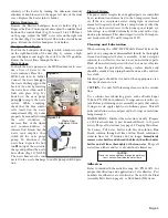
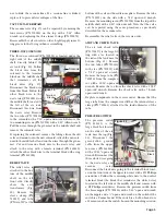
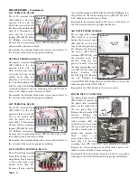
Remove the Electric handpiece from its holder (Fig. 8).
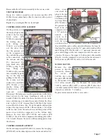
Depress the Foot Control pedal and adjust the middle black
knob on the control block (Fig. 9) to read 30 to 45 PSI max.
on the gauge. Adjust the "HP3" water valve on the right side
of the unit (Fig. 3) to control water flow to the electric hand-
piece. Return the electric handpiece to its holder.
Handpiece Flush Toggle:
To check the handpiece flush toggle switch, which is located
on the right-hand side of the unit (Fig. 3), remove a high-
speed handpiece and toggle the switch to the ON position.
Ensure that water flows through the line.
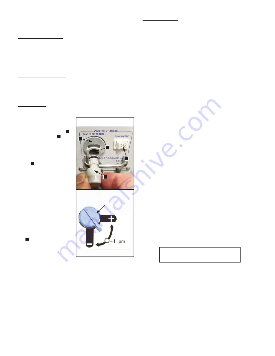
Waste System:
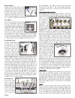
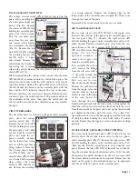
To check the waste pump, use the HVE instrument to vacu-
um a liter of water to the
waste container. Place the
HVE back into its holder.
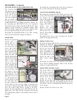
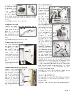
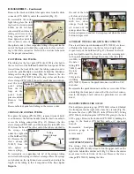
Connect the waste hose to
the waste discharge on the
back of the unit by inserting
the waste hose elbow until it
locks into place (Fig. 11).
Switch on the waste purge
pump to empty the waste
system. While emptying,
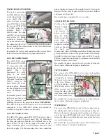
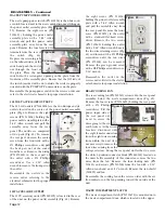
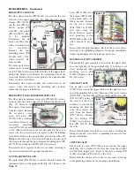
check that the blue control
valve located in the waste
compartment (Fig. 12) works
properly by manually turning
the valve clockwise to
decrease flow of the liquid
and counterclockwise to
increase flow. Ensure that the
waste tank empties, then
switch off the waste purge
pump. To disconnect the
waste hose, depress the but-
ton on top of the waste dis-
charge and pull out the waste
hose elbow (Fig. 11). NOTE:
The waste hose must be con-
nected to the waste discharge to enable pump switch opera-
tion.
C
D
A
B
Electrical System:
The power outlet receptacles and applied parts are controlled
by an isolation transformer tied to the 1-Amp circuit break-
ers. If the rear receptacles, scaler, curing light, or electrical
motor fail to operate, check these 1-Amp breakers. After the
voltage selector switch is set to the proper power input, sys-
tem voltage is controlled internally in the unit with a step-
down/up transformer. This circuit is protected by 20-Amp cir-
cuit breakers for 110V and 10-Amp for 220V.
Cleaning and Lubrication
When servicing the AMC-20CF Mobile Dental System, the
parts of any component disassembled should be thoroughly
cleaned and inspected before reassembly. A hot detergent
solution is an effective cleaner on all non-electrical parts.
Flush all non-electrical parts with clear, hot water. Abrasive
cleaners have the potential to damage surface finishes and
should be avoided. Any wiping should be done with a soft lint-
free cloth.
Electrical parts should be cleaned with an appropriate elec-
trical parts cleaner or air.
CAUTION:
Use only NON-foaming cleansers in the vaccum
lines.
Use a silicone base lubricating grease, such as Parker Super
O-Lube, PN 490006, to lubricate O-rings and seals in the sys-
tem. Before performing any reassembly of parts that contain
O-rings or seals, apply a light coat of silicone grease. This will
make installation easier and prevent the O-rings or seals from
being damaged.
WATER LINES - Disinfect the water lines weekly. Prepare
a 1:10 bleach solution (1 part household bleach to 10 parts
water). Purge all water lines (see page 48,
Purging Water From
the System
). Fill water bottles with bleach solution. Run
bleach solution through all lines. Allow bleach solution to
stand in lines for 10 minutes but no longer:
Immediately
remove water bottles and discard the bleach, then flush water
bottles and all lines thoroughly with clean water.
Purge all
water lines with air and leave dry until next clinical use.
Adhesives
Refer to included Schematic Drawing Set, PN 420872, for
proper identification and application of all adhesives. Part
numbers for adhesives are also listed at the end of the Final
Assembly Parts List on page34, as Not Shown (NS) items.
Waste Flow
Adjustment Valve
Figure 12
CAUTION:
Do not run saline solutions through the water sys-
tem -- saline will corrode the water filters.
Figure 11
C
A
B
D

