Page 51
FINAL INSPECTION AND TESTING -
Procedure for Aseptico AMC-20CF - F-4.10-02-A
(Testing specs subject to change. Refer to latest Schematic
Drawing Set, PN 420872, sheets 31 & 32 for updates.)
EXAMINATION FOR DEFECTS:
• Unit design, construction, operation, and performance not
as specified.
• Hardware components such as pins, screws and fasteners
missing, broken or otherwise damaged.
• Finish not as specified.
• Damage or defects on exterior or interior surfaces present.
• Plating missing which effects function. Plating not free
from blisters, peeling, visible porosity, or other defects.
• Any component fractured, broken punctured, torn, bowed,
deteriorated, or malformed. Any component misplaced or
not in proper alignment.
• Fastening device requiring loosening or removal is swaged,
peened, staked, or otherwise permanently fastened, com-
ponents missing.
• Components do not fit or mate properly.
• Interface fits between components not proper (too loose;
too tight/binding).
• Components not free from defects.
• Removable components cannot be removed or replaced
without difficulty.
• Components not properly assembled or aligned.
• Components do not store or remove from case without dif-
ficulty.
• Handpieces and air hoses when stored coming in contact
with sharp metal edges or surfaces.
• Coarse machine, tool or die marks present.
• Surface not clean, not free of foreign matter, flux or other
defects.
• Damage or defects on exterior or interior surface present.
• Operating instructions not provided.
• Service data not provided.
• Identification markings not present, not complete, not
permanent, not correct.
• Total unit weight not specified
SETTING UP THE UNIT:
Fill water bottles with tap water. Set the voltage selector
switch to 110V. Attach the 110VAC cable to the unit and
110VAC, 60Hz power supply. (Refer to para. H when set-
ting up unit for 220V testing.)
A. Operation Test:
Attach a dental high speed, and low speed handpiece to
the hose connectors. Provide necessary utilities to attach
the saliva ejector mouthpiece and high volume evacuator
tip. Provide 80-100 psi compressed air and necessary water
utilities to the unit input. The handpiece control, fiber
optic lighting system(opt.), oral evacuation, the three-way
syringe, self contained water systems, curing lights and
scaler shall be tested by operating each for two minutes
and then turning them off for one minute. Repeat this pro-
cedure several times, the unit shall be disassembled and
stored in the carrying case without any difficulty.
B. Foot Control Accuracy Test:
Operate a handpiece at a medium speed by means of the foot
control. Increase and decrease the speed by 5 psi (0.35 kgs/cm)
increments by varying the pressure on the foot control.
C. Water Coolant Test:
Attach a dental highspeed handpiece to the highspeed
hose connector(s). Turn the water coolant switch "ON".
Operate handpiece until such time that coolant water
sprays from handpiece outlet in a uniform spray. Adjust
water coolant flow valve from minimum to maximum flow
to verify proper function. Turn the water coolant switch
"OFF". Operate handpiece and verify that water coolant
shuts off. Repeat this procedure for all highspeed(wet)
handpiece controls. To test the anti- retraction feature of
the water coolant, connect a 15.2 cm (6.0 inches) long tube,
0.159 cm (.063 inches)inside diameter to the fitting where
the water tube to the handpiece coupling is normally
attached. With the test hose in vertical position and the
opening facing upward, operate the foot control with the
coolant water on, then shut off the water flow by releasing
the foot control. The meniscus of the water in the test hose
must not recede more than 2 cm (0.8 inches) below the
opening of the hose.
D. Performance Test. (Drive Air):
Attach a dental high speed, and low speed handpiece to the
hose connectors. Run the highspeed handpiece until such
time that the compressor turns on to replenish the air stor-
age tank. At this time before the tank is replenished, adjust
the running pressure to 32 psi required. Run the lowspeed
handpiece until such time that the compressor turns on to
replenish the air storage tank. At this time before the tank
is replenished, adjust the running pressure to 45 psi
required.
E. Performance Test. (Suction):
Attach both the high vacuum and saliva ejector hoses to the
test fixtures. With the vacuum assist on verify that the high
vacuum is at least 4.6 SCFM at 4 in Hg and the saliva is 1.0
SCFM at 1.5 in Hg simultaneous.
F. Auxiliary Outlet:
With the unit on verify that 110V is present at the outlet in
the rear of the instrument.
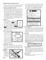
G. Waste Tank Shutoff and Removal:
Vacuum in water until the unit shuts off the compressor.
Attach the waste hose to the rear of the unit and turn on
the waste pump switch. Adjust the waste flow valve and ver-
ify that the flow rate changes accordingly. See
Waste System
on page 3 for step-by-step instructions.
H. Water Selector Toggle
Empty one of the water bottles. Place the toggle valve to
the water bottle that is full and verify that water comes out.
Toggle the valve to the empty water bottle and allow
enough time to purge the line to verify that the system is
drawing from the empty water bottle.
I. Test the 220V operation:
Set the voltage switch to 220V and attach appropriate cable.
Attach the unit to the 220V outlet and run the instrument.
Verify that 220V is present at the European outlets.
J. AEU-5000 Remote Mount Test:
Refer to Schematic Drawing Set, PN 420872, page 32 for
test instructions on the AEU-5000 electric motor assembly.
K. High Pot Tests:
Refer to Schematic Drawing Set, PN 420872, page 33 for
setup instructions and testing parameters for ground bond
and dielectric withstand tests.
L. Serial Number:
Ensure that the instrument has one serial number label
attached under the top cover in the rear left side.

