Page 5
not to kink the vacuum lines. If a vacuum line is kinked,
replace it to prevent later collapse of the line.
VACUUM VALVE REPAIR
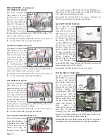
The vacuum valve (Fig. 17) can be repaired by removing the
four screws (PN 510036) on the top with a 5/64" Allen
wrench, and replacing the three inner O-rings (PN 520078).
Reassemble the valve in reverse order. Lightly apply some O-
ring grease to the O-rings when reassembling.
THREE-WAY SOLENOID
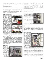
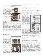
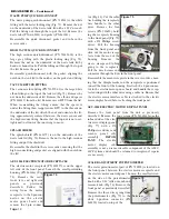
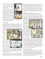
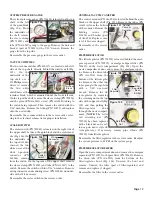
The three-way solenoid (PN 730591) is located under the
right side of the middle
shelf, directly behind the
air tank (Fig. 18). Follow
the black wire from the
solenoid to the terminal
block on the middle shelf
that terminates all the
black wires (Fig. 19).
Disconnect the black wire
from this block. Follow the
other black wire to the
waste relay (PN 800116) on
the middle shelf, located to
the left of the air tank.
Disconnect this wire from
the waste relay. Remove
the two tubes (PN 730130)
to the solenoid with a 7/16" open-end wrench. Remove the
two mounting screws (PN 510506) with a 3/32" Allen wrench.
Pull the wires through the grommet in the middle shelf and
remove the solenoid valve.
If replacing the solenoid, remove the fittings from the old
valve and mount onto the new solenoid. Attach the new sole-
noid to the middle shelf and run the wires through the grom-
met. Cut and trim one black wire to the waste relay and
attach to the relay with a female terminal (PN 860240).
Attach the other black wire to the terminal block with a ring
terminal (PN 860004).
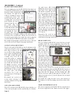
RELIEF VALVE
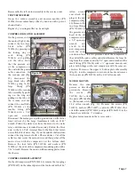
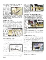
The relief valve is
attached to the bot-
tom of the middle
shelf, on the left
front side, directly
above the auto
transformer (Fig.
20). Remove the
sleeve clamp (PN
730015) and tube
(PN AA-94C) at the
bottom of the valve with needle-nose pliers. Remove the tube
(PN 730130) on the side with a 7/16" open-end wrench.
Remove the mounting screw (PN 510506) from the top of the
middle shelf with a 3/32" Allen wrench. Note that the valve
can be repaired using the same procedure as previously
described for the vacuum valve.
Reassemble the relief valve in the reverse order.
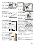
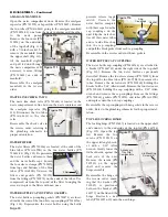
AIR TANK CHECK VALVE
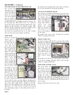
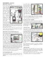
The air tank check valve
(PN 730257) is the large fit-
ting with a tee located on
the side of the tank near the
bottom (Fig. 21). Remove
the two tubes (PN 730130)
to the tee (PN 730119) with
a 7/16" open-end wrench.
Remove the large tube (PN
730256) from the compres-
sor with a 13/16" open-end
wrench. Remove the tee from the check valve with a 11/32"
open-end wrench. Remove the check valve with a 7/8-inch
open-end wrench.
Replace components in the reverse order. Ensure that the
large tube from the compressor still has the internal sleeve
clamp (PN 730261) attached to the inside-diameter of the
tube.
PRESSURE SWITCH
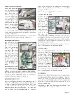
The pressure switch
(PN 830133) is the
large black box located
on the side of the air
tank, near the top (Fig.
22). Disconnect the
green/yellow ground
cable from the upper
fan cover (PN 461864)
with a 11/32" open-end
wrench. Disconnect the
three white wires going
to the waste relay and
vacuum
relay.
Disconnect the black wire going to the terminal block locat-
ed on the front side of the upper fan cover with a #2 Phillips
screwdriver. Follow the remaining white wire to the neutral
terminal block (the block that terminates the white wires)
located on the left side of the middle shelf and remove with
a #2 Phillips screwdriver. Remove the pressure switch from
the brass nipple (PN 730233) with a 9/16" open-end wrench
on the nipple and a ¾" open-end wrench on the switch if the
switch is a Furnas brand. If the switch is a LeFoo brand, use
a 22mm wrench on the switch. Loosen the mounting screw on
Figure 20
Relief Valve
Terminal
Block
Figure 18
Figure 21
Check
Valve
Figure 22
Relays
Pressure
Switch
Terminal
Block
Figure 19
Solenoid

