Page 6
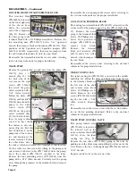
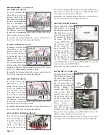
the pressure switch cover with a Phillips screwdriver and
remove cover. Remove the wires from the switch with a #2
Phillips screwdriver and place on the new switch per the elec-
trical schematic. Leaving the cover off, install the new switch
onto the tank and reconnect the wire per the electrical
schematic. Open the top lid on the unit, raise the knob on the
pressure regulator (PN 730598), and then rotate the knob
clockwise to full open. This will allow the user to observe the
system pressure gauge on the top shelf while setting the pres-
sure. Power up the unit. CAUTION: The terminal blocks and
connecting wires are live when the unit is powered up. Refer
to the label inside the pressure switch cover to adjust the cut-
out and cut-in pressure screws. Adjust the cut-out pressure to
110 PSI and cut-in to approximately 80/90 PSI. Readjust the
pressure regulator back to approximately 80 PSI. Reattach
the pressure switch cover. There is also a tank-pressure port
available just below the pressure switch where a gauge can be
installed and used to observe the system pressure: Remove
the port plug (PN 730098) with a ¼" Allen wrench and install
a ¼ NPT pressure gauge of appropriate range. Turn the unit
off and remove the power cord.
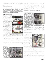
AIR TANK
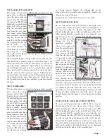
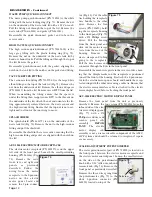
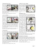
Remove the drain line (PN AA-
95G) from the bottom of the
tank (Fig. 23) with a 7/16" open-
end wrench. Remove the two
lines going to the tee on the
check valve (Fig. 24) with a 7/16"
open-end wrench. Remove the
large tube from the check valve
with a 13/16" open-end wrench.
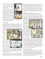
Remove the tube next to the
pressure switch with a 7/16"
open-end wrench (Fig. 25).
Follow the wires from the pres-
sure switch to the waste and vac-
uum relays and remove. Follow
the black wire from the pressure
switch to the terminal block and
remove with a #2 Phillips screw-
driver. Follow the long white
wire to the neutral terminal
block and remove with a #2
Phillips screwdriver. Loosen the
caster under the tank with two
¾" wrenches until the nut is held
onto the caster with minimal
threading. Open the top lid on
the unit and lock in the raised
position. Swing the instrument arms to the left side of the
unit. Remove the two screws (PN 510404) attaching the right-
hand vertical angle (PN 461665) with a 3/32" Allen wrench.
Undo the three clamps (PN 510514) around the tank with a
5/16" socket or a standard screwdriver. Use a 5/32" Allen
wrench to remove the two screws (PN 510477) on both sides
of the angle that attach the upright bracket (PN 461665) to
the chassis. Lift slightly on the top shelf to tilt the upright
away from the unit. Remove the tank. Remove all of the com-
ponents from the old tank and replace onto the new tank. For
tools required, see instructions for the tank components.
Reassemble the air tank in the reverse order
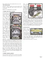
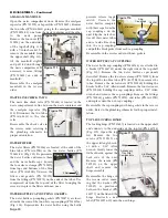
RIGHT VENTURI ASSEMBLY
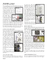
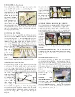
Remove the two mounting
screws (PN 510404) from
under the chassis with a 3/32"
Allen wrench. Remove the vac-
uum tube (PN 730373) from
the vacuum valve assembly
(Fig. 26). Remove the pressure
line (PN 730130) to the venturi
(PN 461851) with a 7/16" open-
end wrench. To remove the
venturi from the bracket (PN
461897), remove the two
screws (PN 510309) from the
bracket with a 3/32-inch Allen wrench. If the venturi is
plugged, it is possible to repair it by removing the elbow fit-
ting (PN 730351) from the venturi nozzle (PN 461852) with a
7/16" open-end wrench on the nozzle and a 9/16" open-end
wrench on the elbow fitting. Then remove the nozzle from the
venturi body with a 7/16" wrench for the nozzle and a ¾"
wrench for the body. Then clean out the orifice in the nozzle
using a drill with a 0.048" diameter bit. Ensure that the orifice
is clear with no chips or burs, which will affect performance.
Reassemble the right venturi assembly in the reverse order.
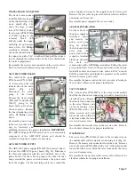
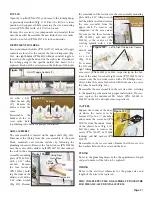
LEFT VENTURI ASSEMBLY
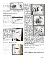
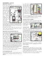
Remove the vacuum tube (PN
730373) coming from the ‘Y’
fitting on the vacuum tube
assembly (Fig. 27). Remove
the pressure line (PN 730130)
with a 7/16" open-end wrench.
Using a pair of needle nose pli-
ers, remove the sleeve clamp
(PN 730015) and clear tube
(PN AA-94C) coming from the
relief valve assembly. Remove
the two screws (PN 510309) holding the venturi body (PN
461851) to the bracket (PN 461869) with a 3/32" Allen
wrench. To repair the venturi, remove the barb fitting (PN
730062) and gasket (PN 730074) from the elbow fitting (PN
730351-01) with a ¼" wrench. Then, follow the same proce-
dure shown above for the right venturi to remove the elbow
and nozzle, and to clean out the orifice in the nozzle.
Figure 23
Tank Drain
Line
Figure 24
Check Valve
Tee
Figure 25
Relays
Tube
Figure 26
Pressure
Line
Venturi
Muffler
Vacuum
Tube
Figure 27
Pressure
Line
Clear
Tube
Vacuum
Tube
Right
Venturi
Muffler
DISASSEMBLY - Continued

