background image


ADR141A / 
ADR241A


Doc ID   : ADR241A_IM_01 

Ref  ID   : ADR241A/IM/PLF 

Rev No.  :  02 

Page No.  :  

67

 of 150 


0.100

1.000

10.000

100.000

1000.000

1.000

10.000

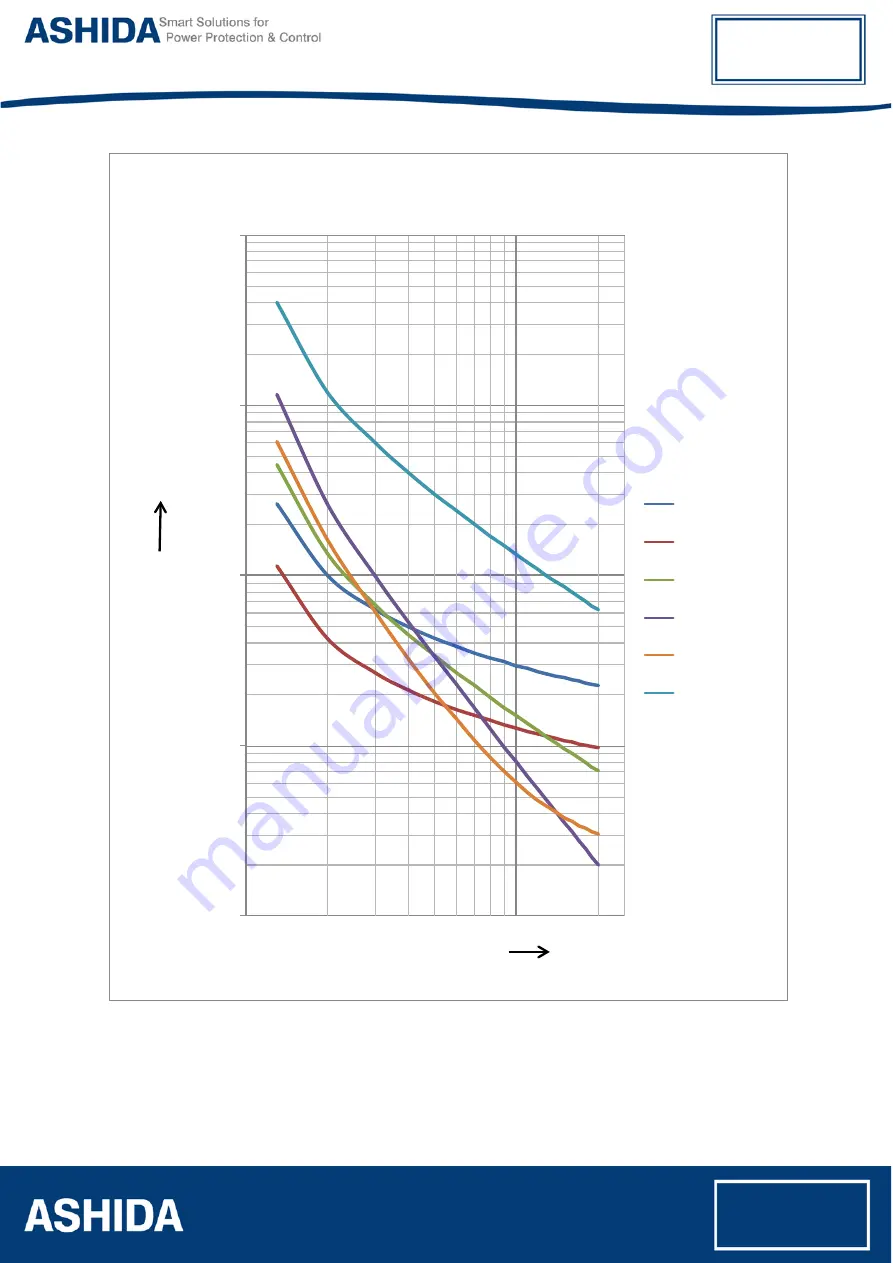
C1 Normal 

Inverse1
C2 Normal 

Inverse2
C3 Very Inverse

C4 Extremely 

Inverse
C4A Extremely 

Inverse
C5 Long Time 

Inverse

Current in Ampere 

ALL IDMT Curves

T

im

e i

n

 s

eco

n

d


Summary of Contents for ADR141A

Page 1: ...Doc ID ADR241A_IM_01 Ref ID ADR241A IM TP Rev No 02 Page No 1 of 150 ADR141A ADR241A ADR141A ADR241A Feeder Protection Relay Instruction Manual...

Page 2: ...to safety install set test and operate the relay functionality The instruction manual can be used by power engineers and other experienced protective relay application persons It is not the intention...

Page 3: ...the Safety Section of the equipment documentation is intended to ensure that equipment is properly installed and handled in order to maintain it in a safe condition It is assumed that everyone who wi...

Page 4: ...ake any action without proper authorization Contact the appropriate person of Ashida Technical Sales office and request the necessary information SYMBOLS AND EXTERNAL LABELS ON THE EQUIPMENT For safet...

Page 5: ...used The equipment must be connected in accordance with the appropriate connection diagram Protection Class I Equipment Before energizing the equipment it must be earthed using the protective conducto...

Page 6: ...ll be used The Listed type shall be a Class J time delay fuse with a maximum current rating of 15A and a minimum D C rating of 250 Vdc for example type AJT15 Where UL or CSA Listing of the equipment i...

Page 7: ...ards Modules and PCB cards must not be inserted into or withdrawn from the equipment whilst it is energized since this may result in damage Insertion and withdrawal of extender cards Extender cards ar...

Page 8: ...ments is 8A high rupture capacity HRC Red Spot type NIT or TIA or equivalent unless otherwise stated in the technical data section of the equipment documentation The protective fuse should be located...

Page 9: ...nted in a specific cabinet or housing which will enable it to meet the requirements of IEC 60529 with the classification of degree of protection IP52 dust and splashing water protected with optional c...

Page 10: ...Page intentionally Left Blank...

Page 11: ...he Goods 32 2 3 Installation Procedure 32 2 3 1 Safe Mounting 32 2 3 2 Relay Connection and Diagram 35 2 3 3 Before energizing the relay following should be checked 35 2 3 4 Relay Operating Condition...

Page 12: ...e Setting 51 3 2 5 Bank Settings 51 3 2 6 History Fault 52 Section 4 PROTECTION FUNCTION LOGIC FUNCTIONS Sr No Description Page No 4 Protection function Logic Functions 56 4 1 Overview 56 4 2 Applicat...

Page 13: ...ynchronisation 88 7 6 Spontaneous Events 88 7 7 General Interrogation GI 88 7 8 Cyclic Measurements 88 7 9 Commands 88 7 10 Configuration 89 7 11 IEC 103 Protocol Mapping 89 Section 8 USER GUIDE Sr No...

Page 14: ...Date Time Settings 119 8 3 10 1 To Set Date Time Settings 119 8 3 10 2 To View Date Time Settings 121 Section 9 FLOW CHART Sr No Description Page No 9 Flow Chart Overview 125 9 1 Main Menu 125 9 2 Fl...

Page 15: ...zing Event and fault Record 139 10 1 Overview 139 10 2 Event recording 139 10 3 History Fault recording 139 Section 11 TESTING AND COMMISSIONING Sr No Description Page No 11 Testing and COMMISSIONING...

Page 16: ...Page intentionally Left Blank...

Page 17: ...ADR141A ADR241A Doc ID ADR241A_IM_01 Ref ID ADR241A IM I S Rev No 02 Page No 17 of 150 Section 1 Introduction and Specifications...

Page 18: ...Doc ID ADR241A_IM_01 Ref ID ADR241A IM I S Rev No 02 Page No 18 of 150 Contents 1 INTRODUCTION AND SPECIFICATIONS 19 1 1 Overview 19 1 2 Features 19 1 3 Technical Specifications 21 1 4 Typical Tests...

Page 19: ...lection of Curve Seven selectable curves Normal Inverse1 C1 Normal Inverse2 C2 Very Inverse C3 Extremely Inverse C4 Extremely Inverse C4A EE equivalent Long Time Inverse C5 and Definite Time C6 Design...

Page 20: ...steps of 0 005 EF 5 250 in steps of 1 EF HF 50 3000 in steps of 1 EF TMS X0 01 x 1 5 in steps of 0 005 Contacts 2NO for TRIP 4NO for Ann 1NO for BF 1C O for TCS Status 2 nos dedicated for TCS and 2 n...

Page 21: ...on Fig2 Ring main feeder application 1 3 Technical Specifications AC Measuring Input I Measurement Accuracy Typical 2 In for Phase and EF II Frequency measurement range 45 Hz 55 Hz 52 52 52 52 52 Appl...

Page 22: ...0 of lower nominal range and 120 of upper nominal range For DC Supply 80 of lower nominal range and 110 of upper nominal range For AC Supply III Nominal Burden on 24 230V Auxiliary Power Supply 24 230...

Page 23: ...60255 151 cl 5 2 or 55ms whichever is greater DT Operation 5 or 55ms whichever is greater Note indicates Reference Condition that is Fault current 2 time above set value II Ground Over current EF For...

Page 24: ...0 C Terminals specification I AC current and Voltage Input Terminals M4 Threaded terminals for ring lug connection Suitable up to 4 mm 2 II Auxiliary Input output Terminals M4 Threaded terminal Suitab...

Page 25: ...to half value 1 2 50 S Source impedance 2 Common Mode 4 KV Differential Mode 2 KV EUT Condition Energized V Pulse Magnetic Field Immunity Test IEC61000 4 9 IEC60255 26 ed3 2013 Class 5 1000A m field a...

Page 26: ...c Test IEC60255 27 At 2kV 50Hz a between all terminals connected together and case earth for 1 minute b Between independent circuits with case earth for 1 minute II Impulse Voltage Test IEC60255 27 Te...

Page 27: ...al axis III Bump Test IEC 60255 21 2 Class 1 1000 bumps direction of 10gn peak acceleration and 16ms pulse duration in each of the two opposite direction per axis as per No of axes 3 IV Shock Withstan...

Page 28: ...Page intentionally Left Blank...

Page 29: ...ADR141A ADR241A Doc ID ADR241A_IM_01 Ref ID ADR241A IM I P Rev No 02 Page No 29 of 150 Section 2 Installation and Procedure...

Page 30: ...following should be checked 35 2 3 4 Relay Operating Condition 35 2 3 5 Current Transformer CT Circuit 35 2 3 6 Insulation and dielectric strength testing 35 2 3 7 Cables and Connectors 35 2 3 8 Power...

Page 31: ...as associated considerations regarding product care and personal safety Caution Before lifting or moving the equipment user should be familiar with the Safety Information chapter of this manual 2 2 2...

Page 32: ...uent unpacking make sure that dust on the carton does not fall inside Avoid storing in locations of high humidity In locations of high humidity the packaging may become impregnated with moisture and t...

Page 33: ...M I P Rev No 02 Page No 33 of 150 Figure 1 Inserting Relay into the panel cut out After inserting the Relay in the Panel fasten the relay to the Panel as shown below Figure 2 Fastening Relay to the pa...

Page 34: ...l mount the protective cover on the relay front panel as shown below Figure 3 mounting protective cover on relay front panel Caution Always use M4x25 screws for Protective Cover fitting After mounting...

Page 35: ...tegrity of the earthing connection 5 Current rating of external wiring applicable as per application 2 3 4 Relay Operating Condition The equipment should be operated within the specified electrical an...

Page 36: ...nnections The wires should be terminated with rings using 90 ring terminals with no more than two rings per terminal The product is supplied with sufficient M4 screws for proper connection M4 I O Term...

Page 37: ...rminal sticker at the rear of the relay The supply range is also mentioned on the Terminal sticker and before energising care should be taken to confirm that the auxiliary supply being wired is within...

Page 38: ...rings per terminal Due to the physical limitations of the ring terminal the maximum wire size user can use is 4 0 mm 2 using ring terminals The wire should have a minimum voltage rating of 300 V RMS...

Page 39: ...f ID ADR241A IM I P Rev No 02 Page No 39 of 150 2 4 Mechanical Dimensions and Electrical Connection 2 4 1 Mechanical Dimensions ADR241A without IP cover Figure 8 Case dimensions for basic version with...

Page 40: ...241A Doc ID ADR241A_IM_01 Ref ID ADR241A IM I P Rev No 02 Page No 40 of 150 2 4 2 Mechanical Dimensions ADR241A with IP cover Figure 9 Case dimensions for basic version without IP cover Note All dimen...

Page 41: ...1A ADR241A Doc ID ADR241A_IM_01 Ref ID ADR241A IM I P Rev No 02 Page No 41 of 150 2 4 3 Electrical Connection diagram for 3Phase 3Wire system Figure 10 Electrical Connection diagram for 3Phase 3Wire s...

Page 42: ...1A ADR241A Doc ID ADR241A_IM_01 Ref ID ADR241A IM I P Rev No 02 Page No 42 of 150 2 4 4 Electrical Connection diagram for 3Phase 4Wire system Figure 11 Electrical Connection diagram for 3Phase 4Wire s...

Page 43: ...Page intentionally Left Blank...

Page 44: ...ADR141A ADR241A Doc ID ADR241A _IM_01 Ref ID ADR241A IM PC SI Rev No 02 Page No 44 of 150 Section 3 PC Software Information...

Page 45: ...3 PC SOFTWARE INFORMATION 46 3 1 Overview 46 3 1 1 Relay Talk Software Features 46 3 1 2 ASHIDA Relay Talk System 47 3 2 ADR241A IED Main Screen 49 3 2 1 Parameter Display 50 3 2 2 IEDs Din Display 50...

Page 46: ...ure 3 1 1 Relay Talk Software Features Connections ADR241A connected to the PC through Front port as well as Rear port Settings Editor Provides online utility to interface with ASHIDA Relay series I O...

Page 47: ...ogram menu Following is the main screen of Relay talk system Figure 1 Main screen of Relay talk system For successful communication setting of relay should match with software settings In relay Talk s...

Page 48: ...150 Now set communication setting it should be match with relay settings After selecting the communication setting click on Apply button Now press the IED button Figure 3 IED Setting Now press the Loa...

Page 49: ...display the relay Settings 4 History Faults It will read all fault data which is also available on LCD display 5 Disturbance Recorder This is used to view the disturbance with the help of waveform as...

Page 50: ...used to view Relay name Version and compatibility NOTE The above features are generally provided with all the ASHIDA Relays but the marked features are not applicable to this product 3 2 1 Parameter...

Page 51: ...isted in the list and depending on their type either pulse or latch the control operation Figure 8 Control Operation 3 2 4 Private Setting These settings for IEDs are displayed along with their curren...

Page 52: ...ayed Figure 11 History Fault The windows Buttons functions are as follows Sr No Name Description 1 Fault Buffer To view the fault buffer number 2 Read Fault To read the fault selected in the fault buf...

Page 53: ...Page intentionally Left Blank...

Page 54: ...ADR141A ADR241A Doc ID ADR241A_IM_01 Ref ID ADR241A IM PLF Rev No 02 Page No 54 of 150 Section 4 Protection and Logic Function...

Page 55: ...No 55 of 150 Contents 4 PROTECTION FUNCTION LOGIC FUNCTIONS 56 4 1 Overview 56 4 2 Application Data 56 4 3 General Settings 57 4 4 Phase Over current Element 50 51 59 4 5 Ground Over current Element 5...

Page 56: ...re setting and logic needed for Breaker failure Trip Circuit Supervision Describes the Trip Circuit Supervision setting and logic needed for Trip Circuit Supervision Phase over current Describes all t...

Page 57: ...k software through the Computer the above settings must be set the same in the Relay Talk software as well as in the IED CT Primary and Secondary Settings The Current transformer setting is required t...

Page 58: ...t Breaker CBNO CBNC R1 R2 S4 S3 Figure 1 Logic Diagram for Trip Circuit Supervision When the CB is closed supervision current passes through the Opto input into the trip coil via CBNO When the CB is o...

Page 59: ...value of current with time delay IDMT DT This function provided with two stages Where Stage 1 IE can be programmed as IDMT or Definite Time DT provided with the Range of 5 to 250 in step of 1 The Stag...

Page 60: ...s t K a I Iref b 1 1 3 0 22 Where t operation time a constant I Input current Iref Current threshold setting b Constant K Time multiplier setting Curve Type Description a b C1 Normal Inverse_1 0 14 0...

Page 61: ..._IM_01 Ref ID ADR241A IM PLF Rev No 02 Page No 61 of 150 0 100 1 000 10 000 100 000 1 000 10 000 TMS 0 1 TMS 0 2 TMS 0 3 TMS 0 4 TMS 0 5 TMS 0 6 TMS 0 7 TMS 0 8 TMS 0 9 TMS 1 0 C1 Normal Inverse_1 Cur...

Page 62: ...ADR241A_IM_01 Ref ID ADR241A IM PLF Rev No 02 Page No 62 of 150 0 0 0 1 1 0 10 0 1 0 10 0 TMS 0 1 TMS 0 2 TMS 0 3 TMS 0 4 TMS 0 5 TMS 0 6 TMS 0 7 TMS 0 8 TMS 0 9 TMS 1 0 C2 Normal Inverse_2 Time in se...

Page 63: ...41A_IM_01 Ref ID ADR241A IM PLF Rev No 02 Page No 63 of 150 0 010 0 100 1 000 10 000 1 000 10 000 TMS 0 1 TMS 0 2 TMS 0 3 TMS 0 4 TMS 0 5 TMS 0 6 TMS 0 7 TMS 0 8 TMS 0 9 TMS 1 0 C3 Very Inverse Curren...

Page 64: ...01 Ref ID ADR241A IM PLF Rev No 02 Page No 64 of 150 0 010 0 100 1 000 10 000 100 000 1 000 10 000 TMS 0 1 TMS 0 2 TMS 0 3 TMS 0 4 TMS 0 5 TMS 0 6 TMS 0 7 TMS 0 8 TMS 0 9 TMS 1 0 C4 Extremely Inverse...

Page 65: ...ef ID ADR241A IM PLF Rev No 02 Page No 65 of 150 0 010 0 100 1 000 10 000 1 000 10 000 TMS 0 1 TMS 0 2 TMS 0 3 TMS 0 4 TMS 0 5 TMS 0 6 TMS 0 7 TMS 0 8 TMS 0 9 TMS 1 0 C4A Extremely Inverse As per EE R...

Page 66: ...1 Ref ID ADR241A IM PLF Rev No 02 Page No 66 of 150 0 100 1 000 10 000 100 000 1000 000 1 000 10 000 TMS 0 1 TMS 0 2 TMS 0 3 TMS 0 4 TMS 0 5 TMS 0 6 TMS 0 7 TMS 0 8 TMS 0 9 TMS 1 0 C5 Long Time Invers...

Page 67: ...IM PLF Rev No 02 Page No 67 of 150 0 100 1 000 10 000 100 000 1000 000 1 000 10 000 C1 Normal Inverse1 C2 Normal Inverse2 C3 Very Inverse C4 Extremely Inverse C4A Extremely Inverse C5 Long Time Inver...

Page 68: ...r If Cold Load function is enable whenever a circuit breaker is turn ON relay sense through CB auxiliary contact CBNO and start internal Cold Load timer during this time period relay will activate sep...

Page 69: ...Page intentionally Left Blank...

Page 70: ...ADR141A ADR241A Doc ID ADR241A_IM_01 Ref ID ADR241A IM MS Rev No 02 Page No 70 of 150 Section 5 Metering Section...

Page 71: ...ADR141A ADR241A Doc ID ADR241A_IM_01 Ref ID ADR241A IM MS Rev No 02 Page No 71 of 150 Contents 5 MEASUREMENT SHEET 72 5 1 Measurement 72...

Page 72: ...se and ground current based on the power system network Parameter Unit Description R 0000 A Primary current in phase R Y 0000 A Primary current in phase Y B 0000 A Primary current in phase B N 0000 A...

Page 73: ...Page intentionally Left Blank...

Page 74: ...ADR141A ADR241A Doc ID ADR241A_IM_01 Ref ID ADR241A IM SS Rev No 02 Page No 74 of 150 Section 6 Setting Sheet...

Page 75: ...ADR141A ADR241A Doc ID ADR241A_IM_01 Ref ID ADR241A IM SS Rev No 02 Page No 75 of 150 Contents 6 SETTING SHEET 76 6 1 Relay Settings 76 6 2 Cold Load 78 6 3 Date and Time setting 79...

Page 76: ...n step of 1 This setting determines Pick up setting for first stage ground over current element 8 IE TMS 1 00 0 01 1 50 in steps of 0 005 This setting for the time multiplier setting to adjust the ope...

Page 77: ...This setting is used to enable turn on or disable turn off Trip circuit supervision This is used to monitor trip coil which is used to trip the circuit breaker 21 Ann Type 1 1 4 This setting is used s...

Page 78: ...IE 100 5 250 in step of 1 This setting determines Pick up setting for first stage Ground over current Measured element 8 CL IE TMS 1 00 0 01 1 50 in steps of 0 005 This setting for the time multiplie...

Page 79: ...or second stage ground over current element 6 3 Date and Time setting Sr No Parameter Defaults setting Settings Ranges 1 SET Hours 00 00 23 Hrs in step 1 Hour setting needed when relay is not connecte...

Page 80: ...Page intentionally Left Blank...

Page 81: ...Doc ID ADR241A_IM_01 Ref ID ADR241A IM CS Rev No 02 Page No 81 of 150 ADR141A ADR241A Section 7 Communication Applicable to ADR241A Only...

Page 82: ...1 1 Function Codes supported 83 7 1 1 2 Exception Codes generated in case of an error 83 7 2 IEC60 870 5 103 87 7 3 Physical Connection and Link Layer 87 7 4 Initialisation 87 7 5 Time Synchronisatio...

Page 83: ...vides more efficient use of the communication bandwidth This mode of communication is defined by the MODBUS standard The IED address and baud rate can be selected using the front panel menu When using...

Page 84: ...ASCII R 4x00031 4x00040 Relay Description 10 20 Bytes ASCII R 4x00075 4x00084 Sr No Function Code Register No of Regs Format Reg Type Address Map 2 Relay Configuration 03 Num Status s 1 16 bit R 4x00...

Page 85: ...L2 1 1 bit R 1x32775 Start Pick up L3 1 1 bit R 1x32776 General Trip 1 1 bit R 1x32777 Trip L1 1 1 bit R 1x32778 Trip L2 1 1 bit R 1x32779 Trip L3 1 1 bit R 1x32780 Trip Ip 1 1 bit R 1x32781 Trip Ip 1...

Page 86: ...s Format Reg Type Address Map 5 Outputs 05 Trip 1 16 bit W 0x33025 LED Reset 1 16 bit W 0x33026 Sr No Function Code Register No of Regs Format Reg Type Address Map 6 Parameters 04 IR 2 32 bit Float R...

Page 87: ...this interface Initialization reset Time synchronisation Event record extraction General interrogation Cyclic measurements General commands 7 3 Physical Connection and Link Layer For connecting on IE...

Page 88: ...tegorized using the following information Function type Information Number The IEC 60870 5 103 profile in the Menu Database contains a complete listing of all events produced by the device 7 7 General...

Page 89: ...NUMBER Status indications in monitor direction 18 Protection active X 1 1 7 9 11 12 20 21 160 19 LED Reset 1 1 7 11 160 145 Relay Error X 1 1 7 9 11 12 20 21 127 21 Test X 1 9 11 127 22 Local Paramet...

Page 90: ...tion 21 Test X 1 9 11 127 69 Trip L1 2 1 7 160 70 Trip L2 2 1 7 160 71 Trip L3 2 1 7 160 90 Trip Ip 2 1 7 160 91 Trip Ip 2 1 7 160 123 Trip Ie 2 1 7 126 124 Trip Ie 2 1 7 126 85 Breaker failure 2 1 7...

Page 91: ...1 127 Sr No INF Description TYP COT FUN 8 Semantics of INFORMATION NUMBER System Function in control direction 0 Initialization of general interrogation 7 9 255 0 Time synchronization 6 8 255 Sr No IN...

Page 92: ...Page intentionally Left Blank...

Page 93: ...ADR141A ADR241A Doc ID ADR241A_IM_01 Ref ID ADR241A IM UG Rev No 02 Page No 93 of 150 Section 8 User Guide...

Page 94: ...100 8 3 1 Default Display 100 8 3 2 Main Menu Details 100 8 3 3 Measurement 102 8 3 3 1 To View Measurement 102 8 3 4 Relay Settings 103 8 3 4 1 To Set Relay Settings 103 8 3 4 2 To View Relay Settin...

Page 95: ...ay tripped by EF Hand Reset HR Type 4 TRIP BF Green LED Indicates that Trip pulse is being executed SR type when TRIP contact selected as SR and HR type when TRIP contact selected as HR Red LED indica...

Page 96: ...ripping occurs 8 1 2 Touch Keys The function of relay is controlled by the following keys provided on the Front Plate Left Arrow When the Left Arrow key is used to navigate through the menus and subme...

Page 97: ...elected as HR Red LED indicates BF operated SR type when BF contact selected as SR and HR type when BF contact selected as HR 8 1 4 RS422 RS485 Port for ADR241A RS422 RS485 Port is provided at the rea...

Page 98: ...to move to the next option Relay Setting Password protected window for Relay Setting setting i e New Password Unit ID IP IP TMS IP IE IE TMS IE IP Curve IE Curve IP C6 Time IE C6 Time IP Delay IE Del...

Page 99: ...sequences 1 Press HW RESET LED RESET Left arrow keys simultaneously 2 Release HW RESET and LED RESET keys while keeping the Left arrow key in press condition Password Fault Memory Clear This message...

Page 100: ...ows actual Primary load current as per the CT Primary selection 8 3 2 Main Menu Details R 0000 Y 0000 B 0000 N 0000 A Default window shows actual Primary load current as per the CT Primary selection P...

Page 101: ...is to view the Fault 1 Press the Plus Up arrow key to move to the next option Fault 2 This window is to view the Fault 2 Press the Plus Up arrow key to move to the next option Fault 3 This window is...

Page 102: ...Measurement 8 3 3 1 To View Measurement Measurement This menu is to view actual load current as per CT Primary and Secondary current selection Press the Right arrow key to move to the next option R 0...

Page 103: ...option New Password 000 Use Inr Dec Editable setting By using the Plus Up arrow key or the Minus Down arrow key the desired New Password can be set The setting range is from 000 to 099 in steps of 1...

Page 104: ...F will be from 00 50 to 3000 in steps of 1 Setting the HF value to 00 will bypass the instantaneous element Press the Left arrow key to move to the next option IE 025 Range 5 250 Editable Setting By u...

Page 105: ...3 Very Inverse 10 Times 1 5 sec C4 Extremely Inverse 10 Times 0 8 sec C4A Extremely Inverse 10 Times 0 6 sec C5 Long Time Inverse 10 Times 13 3 sec C6 Definite Time Inst to 99 9 sec Press the Left arr...

Page 106: ...lay can be selected The setting range for definite time is from inst 00 0 to 99 9secs in steps of 0 1secs This setting is effective only when C6 curve is selected for EF Press the Left arrow key to mo...

Page 107: ...o move to the next option CT Primary 0100 Range 10 5000 Editable Setting By using the Plus Up arrow key or the Minus Down arrow key the desired CT Primary can be set The Setting Range is from 10 to 50...

Page 108: ...s the Left arrow key to move to the next option Ann Cont 001 SR 1 HR 2 Editable Setting By using the Plus Up arrow key or the Minus Down arrow key the desired Annunciation Contact can be set i e 1 or...

Page 109: ...e None Even Odd Editable Setting By using the Plus Up arrow key or the Minus Down arrow key the desired Parity can be set i e None Even or Odd Press the Left arrow key to move to the next option Baud...

Page 110: ...Ip 0100 This window shows the set values of OC Trip OC TMS and OC High Fault Press the right arrow key to move to the next option IE 050 t 0 010 IE 0100 This window shows the set values of EF Trip EF...

Page 111: ...set Test Block and Trip Ckt selection Press the right arrow key to move to the next option Ann Type 001 Ann Cont HR This window shows the set Ann Type and Ann Cont Selection Press the right arrow key...

Page 112: ...Setting By using the Plus Up arrow key or the Minus Down arrow key the desired Cold Load Enable function can be set i e Yes No Press the Left arrow key to move to the next option CL Timer 10 0 Range 0...

Page 113: ...ange is from 5 to 250 in steps of 1 Press the Left arrow key to move to the next option CL IE TMS x0 010 Range X0 01 1 50 Editable Setting By using the Plus Up arrow key or the Minus Down arrow key th...

Page 114: ...Minus Down arrow key the desired CL IE Curve can be selected Seven different types of curves are provided C1 to C6 When the given value is C1 curve 1 is selected and when the given value C2 curve 2 is...

Page 115: ...10s Press the Left arrow key to move to the next option CL IE Delay 00 10 Range 0 10 00S Editable Setting By using the Plus Up arrow key or the Minus Down arrow key the desired CL IE Delay can be set...

Page 116: ...et values of CL OC Curve and CL EF Curve selection Press the right arrow key to move to the next option IP C6 Time 01 0 IE C6 Time 01 0 This window shows the set values of CL OC C6 Time and CL EF C6 T...

Page 117: ...To View Fault 1 Fault 1 This menu is to view Fault 1 Press the Right arrow key to move to the next option I TC 0007 I T This window shows the set values of HF IDMT Fault and Trip Counter Press the ri...

Page 118: ...Setting Error Press LED RESET H W RESET 2 02 EEPROM Error Press LED RESET H W RESET 3 04 RTC Error Set Date Time or Contact Factory 4 04 Timer Error Set Date Time or Contact Factory 5 16 ADC Error Con...

Page 119: ...enu STATUS 8 3 10 Date Time Settings 8 3 10 1 To Set Date Time Settings Date Time Password protected window for Date Time setting i e Set Hour Set Minute Set Second Set Date Set Month and Set Year Pre...

Page 120: ...1 Editable Setting By using the Plus Up arrow key or the Minus Down arrow key the desired SET Date can be set The setting range is from 1 to 31 in steps of 1 Press the Left arrow key to move to the ne...

Page 121: ...w will flash for a moment and it will move to the Main Menu DATE AND TIME 8 3 10 2 To View Date Time Settings Date Time This menu is to view Date Time Press the Right arrow key to move to the next opt...

Page 122: ...Page intentionally Left Blank...

Page 123: ...ADR141A ADR241A Doc ID ADR241A_IM_01 Ref ID ADR241A IM FC Rev No 02 Page No 123 of 150 Section 9 Flow Chart...

Page 124: ...ng 127 9 3 1 To Set Relay Setting 127 9 3 2 To View Relay Setting 128 9 4 Flow Chart Cold Load 129 9 4 1 To Set Cold Load 129 9 4 2 To View Cold Load 130 9 5 Flow Chart TRIP TEST 131 9 6 Flow Chart Fa...

Page 125: ...e displayed and the user can scroll the main menu as given below R 0000 Y 0000 B 0000 N 0000 A Measurement Relay Setting Cold Load TRIP TEST Fault 1 Fault 2 Fault 4 Fault 5 Error Log Status ADR241A V0...

Page 126: ...R241A Doc ID ADR241A_IM_01 Ref ID ADR241A IM FC Rev No 02 Page No 126 of 150 9 2 Flow Chart Measurement 9 2 1 To View Measurement Measurement R 0000 Y 0000 B 0000 N 0000 r 00 00 y 00 00 b 00 00 n 00 0...

Page 127: ...P C6 Time 01 0 Range 0 99 9S IE C6 Time 01 0 Range 0 99 9S IP Delay 00 10 Range 0 10 00S IE Delay 00 10 Range 0 10 00S 5 6 5 6 5 6 5 6 5 6 5 6 5 6 5 6 5 6 5 6 5 6 5 6 5 6 5 6 5 6 BF Delay 200 Range 00...

Page 128: ...0100 Relay Setting IE 050 t 0 010 IE 0100 Ip Normal Inv 1 IE Normal Inv 1 Ip C6 Time 01 0 IE C6 Time 01 0 IP Delay 00 10 IE Delay 00 10 CT Sec 01 A CT Pri 0100 A Ann Type 001 Ann Cont HR Trip Cont HR...

Page 129: ...50 5 Cold Load CL IP 0100 Range 50 3000 CL IE 025 Range 5 250 CL IE Curve C1 Range C1 C6 CL IP C6Time 01 0 Range 0 99 9S CL IE C6Time 01 0 Range 0 99 9S 5 6 5 6 5 6 5 6 5 6 5 6 5 6 5 6 5 6 CL IE 0100...

Page 130: ...C Rev No 02 Page No 130 of 150 9 4 2 To View Cold Load CL Enable NO CL Timer 10 0S Ip 050 t 0 010 Ip 0100 IE 025 t 0 010 IE 0100 Cold Load Ip Normal Inv 1 IE Normal Inv 1 IP C6 Time 01 0 IE C6 Time 01...

Page 131: ...1A ADR241A Doc ID ADR241A_IM_01 Ref ID ADR241A IM FC Rev No 02 Page No 131 of 150 9 5 Flow Chart TRIP TEST 4 I TC 0007 I T R 0000A Y 0000A B 0000A N 0000A 04 07 16 11 51 44 546 6 5 6 5 6 TRIP TEST Fau...

Page 132: ...No 132 of 150 9 6 Flow Chart Fault 1 9 6 1 To View Fault 1 Fault 1 Fault 2 Fault 3 Fault 4 4 I TC 0007 I T R 0000A Y 0000A B 0000A N 0000A 04 07 16 11 51 44 546 Fault 2 6 5 6 5 6 4 3 4 3 4 3 4 3 4 3...

Page 133: ...No 02 Page No 133 of 150 9 7 Flow Chart Error Log 9 7 1 To View Error Log Error Code 000 Error Log 6 6 9 8 Flow Chart Status 9 8 1 To View Status S1 OFF S2 OFF S3 OFF S4 OFF Trip Ckt Healthy Ckt Brkr...

Page 134: ...9 Flow Chart Date Time 9 9 1 To Set Date Time Password 000 Use Inr Dec SET Hrs 012 Range 0 23 SET Mins 10 Range 0 59 SET Secs 020 Range 0 59 5 Date Time SET Date 030 Range 1 31 SET Month 008 Range 1...

Page 135: ...ADR141A ADR241A Doc ID ADR241A_IM_01 Ref ID ADR241A IM FC Rev No 02 Page No 135 of 150 9 9 2 To View Date Time Time 11 12 30 Date 06 08 2015 Date Time 6 6...

Page 136: ...Page intentionally Left Blank...

Page 137: ...ADR141A ADR241A Doc ID ADR241A_IM_01 Ref ID ADR241A IM DR Rev No 02 Page No 137 of 150 Section 10 Analyzing Event and Fault Record Applicable to ADR241A Only...

Page 138: ...A ADR241A Doc ID ADR241A_IM_01 Ref ID ADR241A IM DR Rev No 02 Page No 138 of 150 Contents 10 ANALYZING EVENT AND FAULT RECORD 139 10 1 Overview 139 10 2 Event recording 139 10 3 History Fault recordin...

Page 139: ...tory Faults Recoding All reports are stored in non volatile memory ensuring that a loss of power to the ADR241A will not result in lost data 10 2 Event recording ADR241A relay is providing feature to...

Page 140: ...ADR141A ADR241A Doc ID ADR241A_IM_01 Ref ID ADR241A IM DR Rev No 02 Page No 140 of 150...

Page 141: ...Page intentionally Left Blank...

Page 142: ...Doc ID ADR241A_IM_01 Ref ID ADR241A IM TC Rev No 02 Page No 142 of 150 ADR141A ADR241A Section 11 Testing and Commissioning...

Page 143: ...41A ADR241A Contents 11 TESTING AND COMMISSIONING 144 11 1 Commissioning Test Equipment Required 144 11 2 Checking of External Circuitry 144 11 3 Check Relay Setting 145 11 4 Relay Testing 146 11 5 Pi...

Page 144: ...use Power system Simulator DOBEL make F6150 or any Protective relay ac test source Minimum single phase current source with phase angle control Preferred three phase current source with phase angle co...

Page 145: ...and Earth Fault are entered correctly as per required time grading between feeder and incomer c Ensure instantaneous HF setting done correctly and its definite time delay is applied properly as per re...

Page 146: ...to current injector and timer Following chart shows terminal numbers of connections Source Terminal Relay Terminal Relay Connection Current Source A1 A2 Current R CT _1A A3 A4 Current R CT _5A A5 A6...

Page 147: ...e above procedure for remaining phases and Earth Fault Phase Protection Test Setting IP ________ IP TMS _______ Threshold Theoretical Value Relay Value IP Threshold ________A ________A IP Drop Thresho...

Page 148: ...1 in relay setting menu Set TRIP ANN and BF contact as hand reset HR type Operate the relay by applying current in all three phases and EF Now check the continuity in between NO and C terminals of al...

Page 149: ...ADR241A 11 7 LED Test 1 Apply the auxiliary supply voltage to auxiliary supply terminals the ON LED green will be ON 2 Enable the OC EF instantaneous function and BF function 3 Operate the relay by a...

Page 150: ...c ID ADR241A_IM_01 Ref ID ADR241A IM RS Rev No 02 Page No 150 of 150 REVISION CONTROL SHEET Issue Date Brief description of Revision 01 30 06 2016 Original Version 02 26 10 2016 Mechanical Drawing wit...

Page 151: ......

Reviews: