N U M E R I C A L O C / E F P R O T E C T I O N R E L AY AD R 1 4 1 C / 2 4 1 C
ASHIDA Electronics Pvt. Ltd.
Ref: Manual / ADR141C / 241C
Issue: 04D
Date : 10.07.2014
Page
18/86
8.0
Front Panel and Control
6
7
5
8
1
2
3
4
6
6
7
7
5
5
8
8
1
1
2
2
3
3
4
4
6
7
5
8
1
2
3
4
6
6
7
7
5
5
8
8
1
1
2
2
3
3
4
4
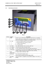
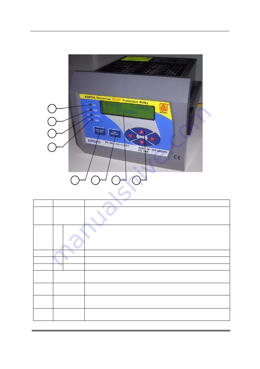
Fig. 4.1
Sr. No. Legend
Description
LEDs
Total 4 bi-colors LED (Red and Green) are provided for user interface.
Some of LEDs are pre defined others are spare and can be programmed
as per the requirement. Following are pre defined LEDs
1 L1
ON
: Green LED indicates Relay OK (Protection Healthy)
: Red LED indicates Fault in following conditions.
1. Problem in relay Hardware.
2. Trip Circuit Fault
2 L2
PKP
: Red LED indicate Start of timer Self Reset (SR) Type
3 L3
FAULT
: Red LED indicate Relay Operated Flag (HR)
4 L4
TRIP
: Green LED indicates Output TRIP relay contact closer (SR) Type
5
LCD display
16 character by 2 line back-lit LCD display will be provided for display of
settings / status and measured value such as line current etc.
6 LED
RESET/EDIT
1 Key provided for LED Reset / EDIT
7
HW Reset
1 key provided for Hardware reset.
This key will be interlocked with LED Reset / EDIT.
8 Navigation
Key
4 keys provided for navigation through different display menu and to do
setting


