background image

N U M E R I C A L   O C / E F   P R O T E C T I O N   R E L AY                                                                                             AD R 1 4 1 C / 2 4 1 C  


ASHIDA Electronics Pvt. Ltd.      

Ref: Manual / ADR141C / 241C 

Issue: 04D 

Date : 10.07.2014   

Page

 22/86 


8.2.2 

Clear Password  

 
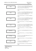
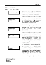
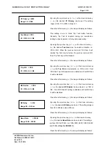
There are unlinking event when user forgets the password, in such case password can be 

cleared by pressing following sequences. 


1)  Press ‘HW RESET’ + ‘LED RESET/EDIT’ and LEFT ARROW KEY (

) this will initialize 

relay hardware.  


2)  Release ‘HW RESET’ + ‘LED RESET/EDIT’ and keeping the left arrow key (

) pressed  

till the following message is display.  This will Reset password to 

‘0’

 (Zero). 


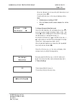
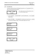
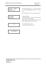
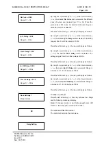
Ashida Digital  

OC/EF Relay 

Fault Memories &   

Password clear  

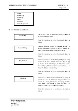
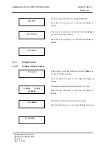
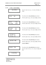
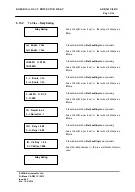
R= 0000        Y = 0000 

B = 0000A 

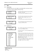
ADR141C – 01.20 

Unit ID = 0001 

R= 0000        Y = 0000 

B = 0000A 

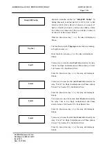
This is default window showing the actual Primary Load 

Current as per “

CT Sec” 

selection 

Summary of Contents for ADR141C

Page 1: ...UMERICAL OC EF PROTECTION RELAY ADR141C 241C ASHIDA Electronics Pvt Ltd Ref Manual ADR141C 241C Issue 04D Date 10 07 2014 Page 1 86 Numerical Over Current Earth Fault Protection Relay Type ADR141C 241...

Page 2: ...this manual at any time and without notice All rights are reserved No part of this manual may be reproduce copied translated or transmitted in any form or by any means without the prior written permi...

Page 3: ...11 6 Self Check Feature 11 7 Technical Details 12 7 1 Technical Specification 12 7 2 Type Test Detail 14 7 3 Cabinet Drawing 16 7 4 Block Diagram 17 8 Front Panel and Control 18 8 1 User s Interface...

Page 4: ...8 3 9 1 To View Fault 1 Data Fault 2 to Fault 8 52 8 3 10 Events Log 53 8 3 10 1 To View Error Log 53 8 3 11 Error Log 53 8 3 11 1 To View Error Log 53 8 3 12 Status 54 8 3 12 1 To View Status 54 8 3...

Page 5: ...67 10 Communication Only for ADR241C Relay 68 10 1 General 68 10 2 General Questions 69 10 3 Physical connection and link layer 70 10 4 Relay Talk System for downloading the data 71 10 5 ADR241C IED M...

Page 6: ...d waveform generated electronics loco motive All these measure values are then used for different protection function such as IDMT DMT Over current protection Instantaneous Over current protection Ear...

Page 7: ...Continuous monitoring of module s internal hardware and alarm generation in case of failure of any critical components 9 4 Digital Output contacts for local alarm as Trip 9 2 dedicated status input f...

Page 8: ...resholds for phase earth over current can be selected with an Inverse Definite Minimum Time IDMT characteristic The time delay is calculated with a mathematical formula where t operation time a consta...

Page 9: ...NUMERICAL OC EF PROTECTION RELAY ADR141C 241C ASHIDA Electronics Pvt Ltd Ref Manual ADR141C 241C Issue 04D Date 10 07 2014 Page 9 86...

Page 10: ...not sufficient DC fail 9 When CB NO and CB NC both active or both inactive CB NO as well as CB NC are both close or open 9 Relay detects any internal hard ware Error B B TC CB NO CB NC To Relay CPU T...

Page 11: ...re within the chip The controller check all the components which are outside of chip such as ADC Non volatile memory used for disturbance data and event non volatile memory used for relay setting real...

Page 12: ...uty user assignable X Contact Rating Continuous 5A Make carry for 0 5 sec 30A Make carry for 3 sec 15A XI Opto Isolated input 1 for CB NO 1 for CB NC XII Thermal With stand for CT 20 x of rated for 3...

Page 13: ...of 0 1Sec IP Settings 50 3000 in steps of 50 IP Delay 0 2 00 Sec in steps of 0 01Sec XVII Earth Fault Section 3Io 3Io Settings 10 250 in steps of 1 3Io Time Multiplier TMS x0 01 x1 00 in step of 0 01...

Page 14: ...n 15ms Repetition rate 300ms Both polarities Ri 50 duration 1 min 5 Surge Immunity Test IEC 60255 22 5 IEC 61000 4 6 class 4 Differential Mode 2kV Common Mode 4kV 1 2 50uS 5 surges of each polarity 6...

Page 15: ...Test IEC 60255 21 2 Class 1 1000 bumps of 10gn peak acceleration and 16ms pulse duration in each of the two opposite direction per axis as per IEC 60255 21 2 class 1 No of axes 3 19 Shock Withstand I...

Page 16: ......

Page 17: ......

Page 18: ...dicates Relay OK Protection Healthy Red LED indicates Fault in following conditions 1 Problem in relay Hardware 2 Trip Circuit Fault 2 L2 PKP Red LED indicate Start of timer Self Reset SR Type 3 L3 FA...

Page 19: ...rns to the main menu When the Left Arrow key is pressed than you are able to enter the setting which can be now modified in the Main Menu using Up Arrow key Down Arrow key When the Left Arrow key pres...

Page 20: ...screen by pressing HW RESET LED RESET EDIT Simultaneously Password 0001 Use Inr Dec To Enter the previously set Password Press the LED Reset Key this will display the curser below the password digits...

Page 21: ...ally return to General Settings OK This window will flash for moment The control will return to the main menu Password 0000 New Password To Change Password New Password Press the LED Reset Key this wi...

Page 22: ...lowing sequences 1 Press HW RESET LED RESET EDIT and LEFT ARROW KEY this will initialize relay hardware 2 Release HW RESET LED RESET EDIT and keeping the left arrow key pressed till the following mess...

Page 23: ...ry Current these are the Main Menus available in this relay Since the LCD Display consist only of 2 Lines the main menu list can be scrolled up or down by using the up arrow key or the down arrow key...

Page 24: ...Trip Ckt BF Enable BF Delay and Frequency Press the down arrow key the relay will display as follows Relay Settings Password protected window for Relay Settings for setting IP Enable IP Range IP TMS...

Page 25: ...t RL1 A RL1 B RL2 A RL2 B RL3 A RL3 B RL4 A RL4 B L1 Green A L1 Green B L1 Red A L1 Red B L2 Green A L2 Green B L2 Red A L2 Red B L3 Green A L3 Green B L3 Red A L3 Red B L4 Green A L4 Green B L4 Red A...

Page 26: ...follows Fault 6 This menu is to view the fifth latest Fault data stored by the relay That is Trip Flags Instantaneous and Phase primary Current Trip Counter TC Fault Date Time Press the down arrow ke...

Page 27: ...e actual load current in Secondary as per the CT Secondary selection Press the down arrow key the relay will display as follows Pri Current This menu is to view the actual load current in Primary as p...
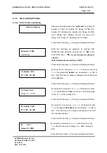
Page 28: ...to communicate with the SCADA computer Press the left arrow key the relay will display as follows CT Sec 5A 1 1A 2 5A By using the up arrow key or the down arrow key the CT Sec setting can be selected...

Page 29: ...lay as follows Trip Ckt YES 01 YES 02 N0 By using the up arrow key or the down arrow key the Trip Ckt can be selected i e YES or NO If set YES then Trip Ckt Supervision is enabled and if set NO then i...

Page 30: ...lay will save the changes and the following message is display Note If changes made are not to be saved press LED Reset or leave key pad untouched for 100 sec Frequency 50Hz Range 50 60Hz By using the...

Page 31: ...etting done previously Press the right arrow key the relay will display as follows CT Sec 1Amp CT Primary 0100A This window will show General Setting done previously Press the right arrow key the rela...

Page 32: ...01 YES 02 N0 By using the up arrow key or the down arrow key the desired IP Enable can be selected i e YES or NO If set YES then IP setting is enabled and if set NO then it will be disabled Press the...

Page 33: ...rrow key the desired 3Io TMS can be set The setting range is from X0 01 1 00 in steps of 0 01 Press the left arrow key the relay will display as follows Ip Curve 006 Range C1 C6 By using the up arrow...

Page 34: ...key or the down arrow key the desired 3Io Delay can be selected The setting range is from 0 to 2 00s in steps of 0 01s Press the left arrow key the relay will display as follows Ip C6 Delay 99 5 Rang...

Page 35: ...y as follows IP Normal Inv 2 3Io Normal Inv 1 This window will show Relay setting done previously Press the right arrow key the relay will display as follows IP 200 t X1 00 IP 800 This window will sho...

Page 36: ...will display as follows CL Enable YES 01 YES 02 N0 By using the up arrow key or the down arrow key the desired CL Enable can be selected i i e YES or NO If set YES then CL setting is enabled and if s...

Page 37: ...he left arrow key the relay will display as follows Ip 001 Multiply by 50 By using the up arrow key or the down arrow key the desired Ip can be set The setting range is multiply of 50 in steps of 1 Pr...

Page 38: ...0 2 00s By using the up arrow key or the down arrow key the desired Ip Delay can be selected The setting range is from 0 to 2 00s in steps of 0 01s Press the left arrow key the relay will display as...

Page 39: ...C6 Delay can be selected Range is in between 0 1 99 9s in steps of 00 1s Press the left arrow key the relay will display as follows Save Settings Mode for save To Save any changes Press the left arrow...

Page 40: ...e previously Press the right arrow key the relay will display as follows IP Enable YES IP Enable YES This window will show Cold Load setting done previously Press the right arrow key the relay will di...

Page 41: ...digital input Binary 0 to Reset Bit Self Reset SR Assign Bit no 9 in Relay LED B as Binary input 0 to set selected function Self Reset Hand Reset HR Assign Bit no 9 in Relay LED B as Binary input 1 to...

Page 42: ...nput CB NO Trip Circuit Supervision Digital input TC Fail Trip Circuit Supervision Faulty TC OK Trip Circuit Supervision OK Proth Trip Circuit Supervision and Internal Hardware OK Error Trip Circuit S...

Page 43: ...want to set Relay 4 for BF SR then you set bit as follow i e RL2 A 0200 RL2 B 0000 Bit Posit 15 14 13 12 11 10 9 8 7 6 5 4 3 2 1 0 A 3Io Trip B Trip Y Trip R Trip B SR HR Bit for A 0 0 0 0 0 0 0 0 1 1...

Page 44: ...Green A 0000 L3 Green B 0000 L3 Red A 01FF L3 Red B 0200 L4 Green A 01FF L4 Green B 0000 Relay LED s config Password protected window for Relay LED confi Setting Password Load fact setting RL1 A RL1...

Page 45: ...s the LED Reset Key it will come out of curser Note The entire detailed information regarding the Bit specification is given below in Bit Definitions Press the left arrow key the relay will display as...

Page 46: ...play as follows L1 Green A 4000 This window shows the Relay LED configuration That is L1 Green A Press the left arrow key the relay will display as follows L1 Green B 0000 This window shows the Relay...

Page 47: ...LED configuration That is L3 Green A Press the left arrow key the relay will display as follows L3 Green B 0000 This window shows the Relay LED configuration That is L3 Green B Press the left arrow k...

Page 48: ...wing message is display Note If changes made are not to be saved press LED Reset or leave key pad untouched for 100Sec OK This window will flash for moment The control will return to the main menu L4...

Page 49: ...as follows L1 Green A 0000 L1 Green B 0000 This window will show Relay config setting done previously Press the right arrow key the relay will display as follows RL2 A 01FF RL2 B 0000 This window will...

Page 50: ...will display as follows L3 Green A 0000 L3 Green B 0000 This window will show Relay config setting done previously Press the right arrow key the relay will display as follows L4 Green A 0000 L4 Green...

Page 51: ...ndow will show Trip flag Press the right arrow key the relay will display as follows R 0000 Y 0000 B 0000A This window will show primary fault current in R Y B Press the right arrow key the relay will...

Page 52: ...t Date Time Press the right arrow key the relay will display as follows I I T This window will show Trip flag Press the right arrow key the relay will display as follows R 0000 Y 0000 B 0000A This win...

Page 53: ...s Error Code 0000 This window will show Error Code detected by self supervision function of Relay Press the right arrow key the relay will display main menu Events Log This menu is to view the Events...

Page 54: ...display as follows Status Status This menu is to view the Status of Digital Input Trip Circuit Supervision circuit breaker and H W S W version Press the right arrow key the relay will display as follo...

Page 55: ...eps of 1 Press the left arrow key the relay will display as follows SET Mins 017 Range 0 59 By using the up arrow key or the down arrow key Minutes can be set The setting range is from 0 59 in steps o...

Page 56: ...key the relay will display as follows Save Setting Mode For Save To save any changes Press the left arrow key the relay will save the change and the following message is display Note If changes made...

Page 57: ...rent This menu is to view the actual secondary load current as per the CT Secondary selection Press the right arrow key the relay will display as follow R 00 00 Y 00 00 B 00 00 This window will show s...
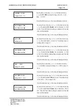
Page 58: ...LAY ADR141C 241C ASHIDA Electronics Pvt Ltd Ref Manual ADR141C 241C Issue 04D Date 10 07 2014 Page 58 86 9 0 FLOW CHART 9 1 Flow Chart To View Primary Current 3Io 0000A R 0000 Y 0000 B 0000A Primary C...

Page 59: ...d 0000 Use Inr Dec CT Sec 001 1 1A 2 5A OK Unit Id 001 General Settings Unit ID 001 Test Block NO Trip Ckt NO Test Block Yes 01 Yes 02 N0 CT Primary 0100 Range 10 3000 BF Enable Yes 01 Yes 02 No Trip...

Page 60: ...Relay Settings Ip Enable NO Ip Enable NO 3Io Enable No 3Io Enable No Ip Curve 002 Range C1 C6 3Io Enable Yes 01 YES 02 NO Ip Delay 0 01 Range 0 2 00s Ip 250 t x1 00 Ip 0100 Ip 250 Range 10 250 Passwo...

Page 61: ...mer 0 50 Ip 250 t x1 00 Ip 1000 3Io Enable Yes 01 YES 02 NO 3Io 250 Range 10 250 Ip Curve 001 Range C1 C6 Ip Enable No Ip Enable No CL Timer 01 00 Range 0 1 10 0S Password 0000 Use Inr Dec Ip Enable Y...

Page 62: ...RL3 A 0077 RL3 B 0000 RL4 A 0088 RL4 B 0000 Load Fact set Yes 01 Yes 02 No Password 0000 Use Inr Dec RL1 B 0000 RL2 A 01FF RL1 A 01FF L1 Red B 0000 L1 Red A 8000 L1 Green B 0000 L2 Red A 0000 L2 Gree...

Page 63: ...Y ADR141C 241C ASHIDA Electronics Pvt Ltd Ref Manual ADR141C 241C Issue 04D Date 10 07 2014 Page 63 86 9 6 Flow Chart To View TRIP TEST Trip Test I I T R 0000 Y 0000 B 0000A 3Io 0000A Trip Count 0000...

Page 64: ...View Faults Note Faults 2 to Fault 8 can be viewed respectively 9 8 Flow Chart To View Events Log Note Events 2 to Events 16 can be viewed respectively Fault 2 Fault 1 I I T R 0000 Y 0000 B 0000A 3Io...

Page 65: ...nics Pvt Ltd Ref Manual ADR141C 241C Issue 04D Date 10 07 2014 Page 65 86 9 9 Flow Chart To View Error Log Settings 9 10 Flow Chart To View Status Settings Error Log Error Code 0000 Status CB NO OFF C...

Page 66: ...10 07 2014 Page 66 86 9 11 Flow Chart To Adjust To View Date Time Settings Password 000 Use INR DEC SET Mins 032 Range 0 59 SET Sec 020 Range 0 59 SET Hrs 04 Range 0 23 Date Time OK Time 04 32 20 Date...

Page 67: ...OC EF PROTECTION RELAY ADR141C 241C ASHIDA Electronics Pvt Ltd Ref Manual ADR141C 241C Issue 04D Date 10 07 2014 Page 67 86 9 12 Flow Chart To View Secondary Current 3Io 00 00 Sec Current R 00 00 Y 00...

Page 68: ...gh different status flags There are two types of status flags 1 Logical status such relay Pick up Relay operation setting change etc these are generated within relay 2 Similarly there is opto coupler...

Page 69: ...ation with unlikely any distortion in the transmission and reception of data The major advantage of RS485 Port is it is multidrop i e upto 32 different devices can be connected to single port 10 2 6 W...

Page 70: ...ted in the higher level protocol to detect the data corruption and resend the information at a later time 10 3 Physical connection and link layer Connection is available for IEC60870 5 103 through the...

Page 71: ...ng is a brief step by step instruction to down load relay data Start Relay Talk program from program menu Following is the main screen of Relay talk system Fig 10 3 For success communication setting o...

Page 72: ...After pressing Configuration button display will show following screen And follow steps Fig 10 4 Now check communication setting Fig 10 5 Adjust Proper Values of CT PT Primary and Secondary Press this...

Page 73: ...HIDA Electronics Pvt Ltd Ref Manual ADR141C 241C Issue 04D Date 10 07 2014 Page 73 86 To finalise setting Press then Press finally Press This will return to main screen Default IDs settings Here we se...

Page 74: ...YA V2 Series ADITYA2_2 Fig 10 7 Summary to ADR241C interface with relay talk system 1 Connect RS485 port on the back of ADR241C to PC through cable 2 Check that relay setting will match to software co...

Page 75: ...e settings of the relay and also edit the settings of the relay 4 History Faults It will read all fault data i e last 5 fault which is also available on LCD display 5 Reset This is used to reset the r...

Page 76: ...n from PC 12 General This is used to view Relay name Version and compatibility 10 5 1 Parameter Display Online Parameters along with their values in units are displayed along with the Date and Time st...

Page 77: ...The control operation is used to control the relays parameters i e either to Reset the LEDs or to open the CB by TRIP command Fig 10 11 This window is not used in ADR241C This window is used to opera...

Page 78: ...ts i e Trip Counter Date Time of the Faults Type of faults and present current values Fig 10 15 The windows Buttons functions are as follows Sr No Name Description 1 Fault Buffer To view the fault buf...

Page 79: ...241C Issue 04D Date 10 07 2014 Page 79 86 10 7 Settings This window is to view and edit the parameter of the relay The setting are of two types General Settings and Bank Settings 10 7 1 General Settin...

Page 80: ...CTION RELAY ADR141C 241C ASHIDA Electronics Pvt Ltd Ref Manual ADR141C 241C Issue 04D Date 10 07 2014 Page 80 86 10 7 2 Bank Settings This window is to view and edit the parameters in Bank settings of...

Page 81: ...A Electronics Pvt Ltd Ref Manual ADR141C 241C Issue 04D Date 10 07 2014 Page 81 86 10 8 Event list This window shows the all events generated in the relay The following picture shows the auxiliary sta...

Page 82: ...10 07 2014 Page 82 86 Following events occurred while relay is in Trip mode when local test Trip is occurred 1 General start pick up ON 2 General Trip ON 3 Test event ON Fig 10 20 When the relay is no...

Page 83: ...perating Time Test For PHASE 3IO Ref Table Phase Trip at 100 and Phase TMS set at Maximum Position To be checked for 5 Amp Set Current at Delay in Sec C1 C2 C3 C4 C5 2N 10A Phase 10N 50A 20N 100A Phas...

Page 84: ...1 5N of pickup setting Definite Time delay settings 0 5 10 0 Observed Delay Phase Observed Delay 3IO Tolerance 5 0 475 to 0 525 9 5 to 10 5 3 Breaker Fail LBB Time Test Set BF Delay mSecs 100 400 800...

Page 85: ......

Page 86: ...Description 01 06 03 2010 Original Version 02 26 08 2010 Communication Details added 03 03 09 2010 Test Report added 04 15 11 2010 Software Version Changed 04A 22 03 2011 IDMT Graph modified 04B 03 1...

Reviews: