N U M E R I C A L O C / E F P R O T E C T I O N R E L AY AD R 1 4 1 C / 2 4 1 C
ASHIDA Electronics Pvt. Ltd.
Ref: Manual / ADR141C / 241C
Issue: 04D
Date : 10.07.2014
Page
45/86
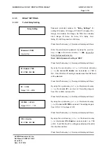
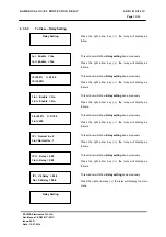
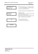
L4 Red A
= 0000
L4 Red B
= 0000
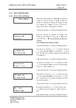
IF Load Factory setting is 02 i.e. NO t
hen the Users can
define the Setting as per his requirements.
Press the LED Reset Key this will display the curser (
⌃
)
below the password digits at Extreme Right ( 0000 ) this
curser (
⌃
) can be shifted right to left and left to right using
the left arrow key (
) and Right Arrow key (
).
By using the up arrow key (
+ /
)
or the down arrow key (
- /
) a given value can be set for each of the digits. The range
is from 0 to F. (The range is from 0000 – FFFF)
When the desired Password or bit is set press the LED Reset
Key it will come out of curser (
⌃
).
Note :The entire detailed information regarding the Bit
specification is given below in Bit Definitions.
Press the left arrow key (
) the relay will display as follows.
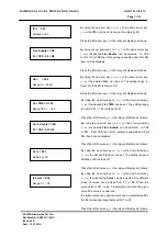
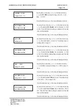
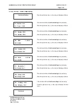
RL1 A = 01FF
This window shows the Relay/LED configuration. That is
RL1 A.
Press the left arrow key (
) the relay will display as follows.
RL1 B = 0000
This window shows the Relay/LED configuration. That is
RL1 B
Press the left arrow key (
) the relay will display as follows.
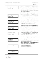
RL3 A = 01FF
This window shows the Relay/LED configuration. That is
RL3 A
Press the left arrow key (
) the relay will display as follows.
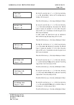
RL2 A = 01FF
This window shows the Relay/LED configuration. That is
RL2 A
Press the left arrow key (
) the relay will display as follows.
RL2 B = 0000
This window shows the Relay/LED configuration. That is
RL2 B
Press the left arrow key (
) the relay will display as follows.

