-13-
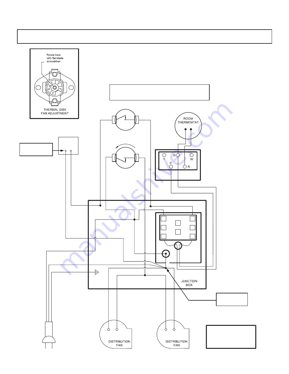
1. DAMPER ACTUATOR DE-ENERGIZES AND REDUCES BURN SETTING
WHEN THE UNIT REACHES TEMPERATURES OF APPROX. 250 DEGREES
2. DISTRIBUTION FANS TEMPERATURE SET-POINT. ADJUSTABE IN APPROX.
5 DEGREE STEPS. A LOW SETTING TURNS THE BLOWER ON SOONER.
THERMAL DISK INFO:
1
3
6
4
COIL
COIL
5
2
DAMPER
ACTUATOR
HIGH
ADJUSTABLE
(Located on top of the box)
(Located below the high
limit disc.)
FAN CONTROL
CENTER FRONT
WHITE
WHITE
WHITE
WHITE
WHITE
BLACK
BLACK
BLACK
RED
RED
RED
BLACK
BLUE
BLUE
BLACK
BLACK
BLACK
GREEN
GROUND
120 VAC
60 HZ
15 AMPS
NOTE: WIRES FROM
DISTRIBUTION FAN RUN
DIRECTLEY INTO THE 4 X 4
JUNCTION BOX.
WHITE
WHITE
WHITE
BLA
CK
BLA
CK
BLA
CK
BLA
CK
WHITE
Thermostatically Controlled Damper Wiring Diagram
*CANADIAN RESIDENTS ARE REQUIRED TO USE THIS KIT FOR INSTALLATION.
This kit includes two red wires. Route the two red wires through the existing conduit that runs from the junction
box up to the T’stat bracket assembly box.
Use large
wire nut here.
Use two small
wire nuts here.
WIRING IS TO BE PREFORMED BY A
QUALIFIED ELECTRICIAN.
Summary of Contents for AF1500E
Page 29: ...29 Notes...
Page 30: ...Notes...


