background image

16 

OPERATING INSTRUCTIONS

MILLIVOLT CONTROL LIGHTING INSTRUCTIONS

1.  STOP! Read the safety information label.

2.  Make sure the manual shutoff valve is fully open.

3.  This gas log set is equipped with an ignition device (piezo) which automatically lights the pilot. If piezo 

ignitor does not light the pilot, refer to instructions for “Match Lighting Instructions”. 

4.  Turn gas control knob clockwise to the OFF position, and turn ON/OFF switch to OFF position.

5.  Wait (5) minutes to clear out any gas. Then smell for gas, including near the 

fl

 oor. If you smell gas, STOP! 

Follow “What to Do if You Smell Gas”. If you don't smell gas, go to next step.

6.  From OFF position, turn the gas control knob counterclockwise to IGN position. Push in control knob for 5 

seconds. NOTE: If you are running the heater for the 

fi

 rst time, it will be necessary to press in the control 

knob for 30 seconds to allow air to bleed out of the gas piping.

7.  With the control knob pushed in, push in and release the piezo ignitor button to light the pilot.

8.  Continue pushing the control knob in for a further 10 seconds to prevent the 

fl

 ame detector from shutting 

off the gas while the probe is warming up. Release the control knob.

9.  Turn gas control knob counterclockwise to the ON position.

10.  After the pilot has been lit for one minute, the burners can be turned on. Turn the ON/OFF switch to ON 

position.

11.  If the burner does not operate, follow the instructions “To Turn Off Gas To Heater” below and call your 

service technician or gas supplier.
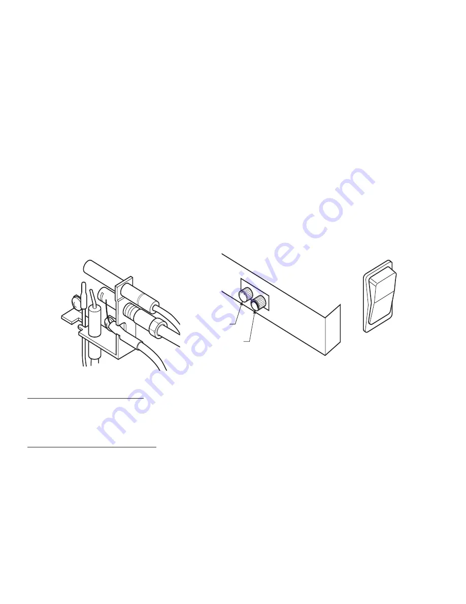
Pilot

OFF

ON

Control Cover Plate for Millivolt 

Hi/Lo Control 

Ignitor/Pilot 
Control

On/Off Switch
(Located on Side of 
Stove) 

TO TURN OFF GAS TO HEATER

1.  Turn ON/OFF switch to OFF position.

2.  Turn control knob clockwise to OFF position to completely shut off the heater.

3.  If applicable: Turn off all electric power to the heater.

MATCH LIGHTING INSTRUCTIONS

1.  Open stove door. Remove any items necessary for easy access to the pilot (for example: logs, screens, 

etc.).

2.  Follow appropriate lighting instructions found previously. Instead of pushing and releasing the piezo 

button, light a match and hold the 

fl

 ame to the end of the pilot and ignite the pilot.

3.  After control knob has been released and pilot stays lit, reinstall any items that were removed for pilot 

access.

4.  Call a quali

fi

 ed service technician for repair or replacement of the piezo ignitor.

Summary of Contents for AGC500VF

Page 1: ...D EXACTLY A FIRE OR EXPLOSION MAY RESULT CAUSING PROPERTY DAMAGE PERSONAL INJURY OR LOSS OF LIFE Certified for installations in the USA Approved for installation in mobile homes Do not store or use gasoline or other flammable vapors and liquids in vicinity of this or any other appliance WHAT TO DO IF YOU SMELL GAS Do not try to light any appliance Do not touch any electrical switch do not use any ...

Page 2: ...oting an unvented gas heater should be cleaned before use and at least annually by a professional service person More frequent cleaning may be required due to excessive lint from carpeting bedding material etc It is imperative that control compartments burners and circulating air passageways be kept clean 8 CARBON MONOXIDE POISONING Early signs of carbon monoxide poisoning are similar to the flu w...

Page 3: ... This is a normal and temporary occurrence The initial break in operation should last two to three hours with the burner at the highest setting Provide maximum ventilation by opening windows or doors to allow odors to dissipate Any odors remaining after this initial break in period will be slight and will disappear with continued use 21 Input ratings are shown in BTU per hour and are for elevation...

Page 4: ... for LP systems IGNITION CONTROLS Piezo ignitor allows ignition of the pilot without the use of matches Millivolt control has four 4 positions OFF All gas to the burner is shut off at the valve IGN Valve position to light maintain a standing pilot ON Valve position to turn burners ON OFF LOW HI Variable position to control flame height heat output Both front and rear burners are in operation to pr...

Page 5: ...5 B C A DIMENSIONS A 26 660mm B 16 406mm C 29 737mm ...

Page 6: ...AN WILL NEED FOR INSTALLATION You must have the following items available before proceeding with installation External regulator for Propane LPG or high pressure natural gas 1 to 2 psi system Piping which complies with local codes Sediment trap recommended Pipe wrench Pipe sealant approved for use with propane LPG resistant to sulfur compounds Manual shutoff valve Tee joint Screwdrivers WARNING DO...

Page 7: ...THE FRONT OF THE HEATER FOLLOW THESE INSTRUCTIONS CAREFULLY TO ENSURE SAFE INSTALLATION FAILURE TO FOLLOW INSTRUCTIONS EXACTLY CAN CREATE A FIRE HAZARD THE APPLIANCE CANNOT BE INSTALLED ON A CARPET TILE OR OTHER COMBUSTIBLE MATERIAL THE APPLIANCE SHALL BE INSTALLED ON A NONCOMBUSTIBLE MATERIAL PANEL EXTENDING THE FULL WIDTH AND DEPTH OF THE APPLIANCE D Minimum to Either Side Wall E Minimum A G G D...

Page 8: ...CLEARANCES HEIGHT REQUIREMENTS Alcove Minimum Dimensions Height From Hearth Width Depth A B C 52 34 36 NOTE Maintain minimum side and back clearances when placing stove in alcove A C B Alcove Installation ...

Page 9: ... lifting technique when positioning the appliance for assembly and installation Leg is removed for pictorial purposes only ON OFF LOGS Wrapping Straps Pallet STEP 1 Remove the two 2 straps and open the wrapping Slide the bag to the bottom of the unit STEP 2 Lift up on the ash lip Pivot it back and down to open the control door ...

Page 10: ...ngly suggested Please use proper lifting technique when positioning the appliance for assembly and installation STEP 5 Remove log box from inside of unit Lift unit off pallet Lift unit up high enough to clear upright supports unit is sitting on STEP 6 Reverse steps 2 4 to reinstall the screen and front of the stove Screen UP BACK STEP 4 Remove the two screws located at the bottom of the screen as ...

Page 11: ...ce controls and burners Failure to do so could prevent the appliance from operating reliable NOTICE A qualified gas appliance installer must connect the heater to the gas supply Consult all local codes IMPORTANT Hold heater valve firmly with a wrench to prevent movement when connecting to inlet pipe Always use an external regulator for all propane LPG heaters and high pressure one to two pound sys...

Page 12: ...als as indicated A Complete Millivolt System Check A Reading Thermostat contacts CLOSED Control Knob ON Main burner should turn ON a If the reading is more than 100 millivolts and the automatic valve still does not come on replace the control b If the closed circuit reading A reading is less than 100 millivolts determine cause for low reading proceed to Section B below B Thermopile Output Reading ...

Page 13: ...tuds 2 Install left bottom log 2 on left log support bracket in front of back log 3 Install right bottom log 3 on right log support bracket in front of back log 4 Install top left log 4 on top of left bottom log 5 Install top right log 5 on top of right bottom log CAUTION During initial operation of the new heater burning logs will give off a paper burning smell and orange flames will be present S...

Page 14: ...the figure below for incorrect shape of pilot flame MILLIVOLT CONTROL BURNER FLAME In normal operation at full rate after 15 minutes the following flame appearances should be observed The left and right rear flames should be yellow and extend 1 2 above middle logs The yellow flames should not contact the logs There should be glowing embers on the front surface of the middle log NOTE The flames and...

Page 15: ...OR LOSS OF LIFE A This appliance is equipped with an ignition device which automatically lights the pilot If the piezo is not working properly refer to Match Lighting instructions B BEFORE OPERATING smell all around the appliance area for gas Be sure to smell next to the floor because some gas is heavier than air and will settle on the floor WHAT TO DO IF YOU SMELL GAS Turn off all gas to the appl...

Page 16: ...to prevent the flame detector from shutting off the gas while the probe is warming up Release the control knob 9 Turn gas control knob counterclockwise to the ON position 10 After the pilot has been lit for one minute the burners can be turned on Turn the ON OFF switch to ON position 11 If the burner does not operate follow the instructions To Turn Off Gas To Heater below and call your service tec...

Page 17: ... or vacuum with brush attachment Vacuum loose particles and dust from the front and rear burners control and piezo covers and grate weldment Inspect and clean burner air intake holes Remove lint or particles with vacuum brush or pipe cleaners Failure to keep air intake holes clean will result in sooting and poor combustion External case should be dusted and wiped with a moist cloth Annual Cleaning...

Page 18: ... from paint hair spray glues etc 2 Gas leak 3 Initial burn off 1 Ventilate room Stop using odor causing products while heater is running 2 Locate and correct all leaks 3 Ventilate room and turn unit on high until odor is gone Odor should be gone after 6 hours of continuous use Appliance shuts off during use 1 Not enough fresh air is available for ODS pilot to operate 2 Low line pressure 3 ODS pilo...

Page 19: ...ow 1 Clean orifice 2 Replace burner orifice 3 Contact qualified service person Burner backfires during combustion 1 Manifold pressure is too low 2 Burner orifice is clogged 1 Contact local gas company 2 Clean burner or replace burner orifice Slight smoke or odor during initial operation 1 Burner orifice is clogged or damaged 2 Burner is damaged 3 Gas regulator defective 1 Clean burner or replace b...

Page 20: ...20 REPLACEMENT PARTS Burner Assembly 3 4 5 6 7 8 9 10 1 11 12 13 2 6 13 8 10 11 12 9 3 4 5 ...

Page 21: ... 89761 Piezo Ignitor 1 2 81211 11 5 16 Union Tee 1 3 81211 05 Front Burner 1 4 81211 06 Rear Burner 1 5 81196 LP Control Valve 1 81198 NAT 1 6 89922 LP ODS Pilot Assembly 1 7 89921 NAT 1 8 81212 14 On Off Switch 1 9 81211 12 VF Valve Tube 1 10 81211 13 VF Rear Burner Tube 1 11 81211 14 VF Front Burner Tube 1 12 81210 08 Upper Burner Orifices NAT 47 1 13 81210 15 Lower Burner Orifices NAT 47 1 14 8...

Page 22: ...llation of hard wired carbon monoxide detectors In the event that the side wall horizontally vented gas fueled equipment is installed in a crawl space or an attic the hard wired carbon monoxide detector with alarm and battery back up may be installed on the next adjacent floor level In the event that the requirements of this subdivision can not be met at the time of completion of installation the ...

Page 23: ...d side wall horizontally vented gas fueled equipment does not provide the parts for venting the flue gases but identifies special venting systems the following requirements shall be satisfied by the manufacturer The referenced special venting system instructions shall be included with the appliance or equipment installation instructions and The special venting systems shall be Product Approved by ...

Page 24: ... all further warranty obligations are thereby met 3 Parts and or service replacements made under the terms of this warranty are warranted only for the remaining period of the original heater warranty 4 Without speci c written exclusionary waivers no one has authority to add to or vary this limited warranty or to create for United States Stove Com pany any further obligation of liability in connect...

Page 25: ...25 NOTES ...

Page 26: ... NAMEPLATE ATTACHED TO THE HEATER WHEN ORDERING REPAIR PARTS ALWAYS GIVE THE FOLLOWING INFORMATION AS SHOWN IN THIS LIST 1 THE PART NUMBER_____________________________ 2 THE PART DESCRIPTION ________________________ 3 THE MODEL NUMBER __________________________ 4 THE SERIAL NUMBER ___________________________ HOW TO ORDER REPAIR PARTS United States Stove Company 227 Industrial Park Road P O Box 151...

Page 27: ..._______ Reason for Purchase Alternative Heat Main Heat Source Decoration Cost Other _________________________ What was the determining factor for purchasing your new appliance _______ I have read the owner s manual that accompanies this unit and fully understand the Installation Operation and Maintenance of my new appliance Print Name Signature Date Please attach a copy of your purchase receipt Wa...

Page 28: ... CUT HERE CUT HERE Fold Here Fold Here United States Stove Company P O Box 151 South Pittsburg TN 37380 Fold Here PLACE STAMP HERE ...

Reviews: