background image

Operating Manual - Pema Protea Equipped Media Amplifier

20

changes to an individual preset can be saved to the amplifier using <Preset Options/Save Preset To Protea>, or saved to the 
PC using <Preset Options/Save To Disk>. Sub Presets (collections of DSP parameters individually selected from software) are 
saved in a similar fashion. 

Presets can be recalled to the Pema amplifier using the following methods:

1) 

Protea

ne 

Software - 

Use a direct or network Ethernet connection from the amplifier to a PC using Protea

ne


software. 

Click (Preset Options >Recall From Disk/Recall From Protea) to load a stored preset into the amplifier. 

2) 

Contact Closure

 - The four contact closure connections on the amplifier back panel allow for amplifier presets #1-4 

(presets already saved and stored in the amplifier memory) to be loaded into the Pema amplifier at the instant a remote switch 
connected to one of pins 1-4 is connected to its ground pin. 

3) 

WR-5

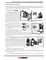
 - A WR-5 will appear in software as a captive device to its host amplifier. The six buttons on the WR-5 can be 

programmed to recall a specific amplifier preset, or scroll through a defined list of presets. 

4) 

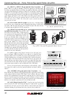
neWR-5

 - A neWR-5 will appear in the software menu tree as a device on the network, and must be assigned to the 

Pema amplifier under control. Like the WR-5, the six buttons on the neWR-5 can be programmed to recall a specific amplifier 
preset, or scroll through a defined list of presets. 

5) 

Event Scheduler

 - Protea

ne 

software offers an event scheduler for several key Pema amplifier functions including preset 

recall. With the event scheduler, the installer can assign one or more times of day or days of the week for the Pema amplifier to 
automatically recall and load a new preset.

6) 

iPad

 - A Preset Recall function can be part of an iPad design.

Caution:

 A new preset may have dramatically different settings capable of damaging sound system components, so be 

careful not to recall the wrong preset while the system is on.

   4.2d Remote Gain Control

1) WR-1 DC Level Control

 - The WR-1 remote potentiometer functions as if it were a front panel attenuator but in a 

remote location. Attenuation from a remote DC level control attenuator is cumulative with all other attenuation for a given 
channel, including the front panel level control.

2) WR-5

 - WR-5 buttons can be individually programmed to select single or multiple input or output channels for remote 

gain control. A gain range with a top and bottom limit can also be set for each gain button. 

Note: To use this feature, a (ne)WR-5 

Remote Gain tool must be placed in one of the DSP processing blocks of the channels(s) to be controlled.

 Refer to section 3.4d, 

item #2.

3) neWR-5

 - The neWR-5 uses an Ethernet network connection instead of the amplifier's data port. Buttons are assigned 

gain control function in the same manner as the WR-5. 

4) RD-8C

 - RD-8C faders are programmed from Protea

ne 

software once the RD-8C is wired to a Pema amplifier Data 

port. The RD-8C will appear in the software Ashly Network device tree as a captive device to the host Pema. Place a Remote 
Gain function in the Pema DSP tab's input or output to assign fader control for that channel or group of channels. The RD-8C 
also has a mute button for each fader which will mute all associated channels. 

5) FR-8/FR-16

 - FR-8/16 faders are programmed from Protea

ne 

software after the remote is connected to the network 

shared with Pema. The FR-8/16 is found in the software Ashly Network>Ashly Remotes device tree. Assign individual fader 
control after selecting the targeted Pema amplifier, then select Mixer, I/O Level, or A/B Source Select mode for each fader. 
Fader Scaling is available to set upper and lower limits.

6) Event Scheduler

 - Protea

ne 

software offers an event scheduler for several Pema amplifier functions including changes 

to WR-5 and neWR-5 remote control gain. With the event scheduler, the installer can assign one or more times of day or days 
of the week for the Pema amplifier to automatically change WR-5 and neWR-5 channel gain parameters.

Summary of Contents for Pema 4125

Page 1: ...Y AUDIO INC 847 Holt Road Webster NY 14580 9103 Phone 585 872 0010 Toll Free 800 828 6308 Fax 585 872 0739 ashly com Protea Equipped Media Amplifier pema 8250 pema 8125 pema 4250 pema 4125 Operating Manual ...

Page 2: ...sed to rain or moisture does not operate normally or has been dropped 1 Lisez ces instructions 2 Conservez ces instructions 3 Observez les avertissements 4 Suivez ces instructions 5 Pour réduire le risque de feu ou la décharge électrique ne pas exposer cet appareil pour pleuvoir ou l humidité 6 Ne pas utiliser l appareil près de l eau 7 Le nettoyer à l aide d un tissus sec 8 Ne pas bloquer les ouv...

Page 3: ...ent Scheduler 16 3 4h Fault Log 16 4 Pema Remote Control 17 4 1 Remote Control Devices 17 4 1a WR 1 Level Control 17 4 1b WR 1 5 Level Control and Preset Recall Switch 17 4 1c WR 2 Preset Recall Switches 17 4 1d WR 5 Programmable Button Control and RPS 18 Remote Power Supply 17 4 1e RD 8C or RW 8C Programmable Fader Controller 18 4 1f INA 1 Inline RS 232 Adapter 18 4 1g neWR 5 Networked Programmab...

Page 4: ...Ashly Remote app for iPad Passive remote control options include remote standby contact closure preset recall and remote DC level control Front panel attenuators and metering Five year warranty About Ashly AshlyAudio was founded in 1974 by a group of recording engineers concert sound professionals and electronics design ers The first products were elaborate custom consoles for friends and associat...

Page 5: ...ng Always use high quality shielded cable for input signals and use balanced input signal when possible To avoid possible system noise or oscillation avoid running low level signal wires parallel to speaker outputs or AC wiring especially over long distance Before testing the system double check all connections and settings Refer to the specifications section of this manual for input output Ethern...

Page 6: ...ashing yellow LED Data indicates that data is flowing to or from the amplifier 2 4 Front Panel Features 1 Mounting Holes For rack mounting 2 Power Switch Switches the unit on or off Note The power switch can be disabled from Proteane Software 3 Status LEDs Indicate status of Power Standby Protect Power Switch Disable and Com activity 4 Air Inflow Vents Cool air enters here and is vented out throug...

Page 7: ...ier to be part of a CobraNet or Dante digital audio network 7 Preamp Outputs These Euroblock connectors provide access to post DSP preamp signals for each channel and are used to drive other amplifiers or processors with the same signal that is driving the power amplifier The preamp outputs are pseudo balanced meaning they use single ended signal with balanced impedance and can be wire balanced or...

Page 8: ...l and in Proteane software which reduces audio output level until the overcurrent condition is no longer present 3 PROTEAne CONTROL SOFTWARE 3 1 Installing Software Ashly Proteane software is included on a CD with each unit Software updates may become available on the Ashly web site Autorun will launch the application ProteaSystemSoftwareNE to install the software Once the software has been instal...

Page 9: ...nd then click Identify which will flash the Com LED on that unit s face panel for two seconds The project canvas is used to visually represent a sound system installation and can display any of the networked Ashly processors amplifiers and remotes used in that system The user can also place an assortment of isolated control objects such as level faders single LEDs meter bars etc and map them to sp...

Page 10: ...er up after other system components have turned on and stabilized Note that the ampli fier must first be on for this change to take effect Power On Delay does not work when standby mode is activated by contact closure 4 Sample Rate and Master Clock Source Selection Changes to both of these settings can be made by clicking the ShowAdvanced Control box in this menu item Sample rate can be set to eit...

Page 11: ...sound system components so be careful not to recall the wrong preset while the system is on 3 4 Device Control Tabs The following device control tabs are available for each Pema device The tabs include Control Surface Security Net work Properties DSP Input Source Meters Meter Dynamics Meters AutoLeveler Metering Event Scheduler and Fault Log 3 4a Control Surface This is the main user interface for...

Page 12: ...as the amplifier front panel clip mute LED Mute Button This button mutes the output channel Output mute can be controlled by the event scheduler Polarity Button This button inverts the polarity of the output channel signal Main Output Channel Fader This controls the output attenuation Output attenua tion below 40dB mutes the output Input Meter This indicates the signal level in dBu as in arrives a...

Page 13: ... attenuators set to this optimal setting of 14 dB 3 4b Security Tab Password protected user access is set up in the security tab User names and password are stored within the Pema amplifier User access is defined by the primary user admin or default Available security levels are View only DSPOutput Channels Access DSP Input Channels Access Preset Recall Access Audio Parameter Access Audio Only Ac ...

Page 14: ...r input and output channels is indicated as a percentage at the bottom of each input section in the DSP tab Increasing the number and complexity of applied DSP tools increases the DSP usage Total DSP usage per group of four channels cannot exceed 100 Available DSP tools include 1 Dynamics controls Brick Wall Limiter Compressor Autoleveler Ducker and Noise Gate Ambient Noise Compensation is availab...

Page 15: ...o Mixer For a given amplifier output all inputs that have been routed to that channel in the matrix router are mixed together here This is also where individual channels can be selected as part of an automix group The automixer function is a gain sharing type automixer which automatically makes smooth gain transitions on all selected automixer input channels to achieve a constant total system gain...

Page 16: ... actions to occur based on the time of day or day of the week Scheduled events can include Preset Recall Power Status Change Channel Mute Output Source Select and certain remote control settings Up to 100 events can be scheduled The Pema date and time can be manually set by the user or linked to the host PC All event schedule data is stored on the amplifier A common use of the event sched uler wou...

Page 17: ...ws selection of one of four presets via inter lockingpushbuttonswitches Eachpushbuttonswitchcan be connected to a Preset Recall Pin on the back panel of the controlled Pema amplifier The terminal numbers correspond to the first 4 Preset Memory locations in the controlled amplifier Pressing a button will select the corresponding preset Windows are provided for a user generated label 4 1d WR 5 Progr...

Page 18: ...s to cover the neWR 5 electrical box and satisfy the aesthetic needs of the installation The neWR 5 appears in the Proteane software device menu tree and must be assigned within its neWR 5 device window to a specific Pema amplifier under control The neWR 5 has six programmable function buttons which can light up green red or amber to display status Further information on LED status is found in the...

Page 19: ...hen the two Euroblock pins labeled Remote Standby on the back of the amplifier are wired to a switch and connected the amplifier goes into Standby mode meaning the amplifier is active but not fully powered up For remote standby to work the power switch must be turned on OR be disabled through Proteane soft ware Open the switch to remove the amp from remote standby mode 2 Proteane Software On Stand...

Page 20: ... not to recall the wrong preset while the system is on 4 2d Remote Gain Control 1 WR 1 DC Level Control The WR 1 remote potentiometer functions as if it were a front panel attenuator but in a remote location Attenuation from a remote DC level control attenuator is cumulative with all other attenuation for a given channel including the front panel level control 2 WR 5 WR 5 buttons can be individual...

Page 21: ... mute inputs or outputs in real time from within the software control surface the DSP section inputs and outputs and the input source section 6 iPad A Mute button can be part of an iPad design 4 2f Remote Zone Source Selection 1 WR 5 WR 5 buttons can be programmed to select different input sources for one zone Azone is typically one or more amplifier output channels driving speakers in a single li...

Page 22: ... dynamics and any gain tool settings in the DSP section allowing signal to pass properly 6 Is the signal properly routed to the desired output in the DSP cross point matrix sec 3 4d 7 Is the level fader set properly in the DSP output channel mixer 8 Did the event scheduler change a preset or the output channel source sec 3 4g Attenuators Don t Work 1 In the device software control surface are the ...

Page 23: ...r power injector providing sufficient Power Over Ethernet PoE or using an external power supply sec 4 1e 3 Is the neWR 5 assigned within its device window to control the desired amplifier 4 Is the neWR 5 hardware lockout switch being used disabling all buttons sec 4 1e 5 If using neWR 5 for gain control be sure to install a ne WR 5 Remote Gain function in a DSP gain block on the channel to be cont...

Page 24: ...1 8 power pink noise 232 232 444 444 341 341 700 700 BTU hr Max 1 3 power sine wave 251 251 481 481 378 378 775 775 Input Sensitivity low Z models 4Ω 3 2dBu 3 2dBu 3 2dBu 3 2dBu 6 2dBu 6 2dBu 6 2dBu 6 2dBu Input Sensitivity 70V and 100V models 7 2dBu all 70V and 100V models Voltage Gain low Z models 26dB all low Z models Voltage Gain 70V models 32dB all 70V models Voltage Gain 100V models 35dB all...

Page 25: ...pecifications Input Source Selection Mic Line Preamp Gain 0 20dB 40dB 60dB Input Source Select Options Analog Auto net analog Dynamics Brick Wall Limiter Threshold 20dBu to 20dBu Ratio infinite Attack 0 2ms dB to 50 ms dB Release 5ms dB to 1000ms dB Compressor Threshold 20dBu to 20dBu Ratio 1 2 1 to infinite Attack 0 2 to 50ms Release 5ms dB to 1000ms dB Detector Peak Average Attenuation Bus 2 ava...

Page 26: ...Filter Modes Float Restricted Manual Filter Type Notch Parametric Filter Frequency Range 20Hz to 20kHz Filter Level Notch Filter Parametric Filter 15dB to 30dB Filter Bandwidth 0 016 to 3 995 Octave Detector Sensitivity five levels Float Time 5 minutes to 24 hours FIR Filter Output only 48kHz only input FBS is disabled on channel using output FIR File types csv fir Crossover 2 Way 3 Way 4 Way Cros...

Page 27: ...vements upon this product without any obligation to install the same on products previously manufactured Any implied warranties which may arise under the operation of state law shall be effective only for FIVE years from the original date of purchase of the product ASHLY AUDIO INC shall be obligated to only correct defects in the product itself ASHLY AUDIO INC is not liable for any damage or injur...

Page 28: ...5 872 0010 Fax 585 872 0739 Toll Free 800 828 6308 ashly com 2014 by Ashly Audio Corporation a Division of Jam Industries Ltd All rights reserved worldwide All features specifications and graphical representations are subject to change or improvement without notice All Trademarks referred to herein are the property of their respective owners ...

Reviews: