ASI DOORS, INC.
(800) 558-7068
asidoors.com
15
Light Curtains & Photo-Eyes
INS
TALL
ATION
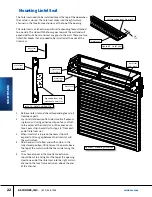
Figure 25: Light Curtain & Photo-Eye Detail
If a light curtain or photo-eye option was ordered, light cur-
tains or photo-eyes will be installed at the factory Light cur-
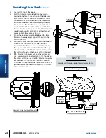
tains are held in position with two locking cams at the top &
bottom (figure 23)
Light curtains are mounted in the face frame covers in a
channel on the opening side of the extrusion Photo-eyes are
mounted in a channel in the face frame base extrusion (figure
24)
Wire leads from the light curtains or photo-eyes will be run up
the length of the face frame, and out the top of the channel
Wire these leads into the control system for photoeye control,
per the schematic for the door
Light curtains or photo-eyes can also be added to an existing
door in the field If you are field installing light curtains or
photo-eyes, install per (figure 23 & 24), and wire them to the
control system per the schematic for the door
Channel
Cover
Leads from Light
Curtains / Photo-Eye(s)
Figure 24: Photoeye And Light
Curtains Installation Options
Light curtain installed in
face frame cover
extrusion
Single or dual photo-eye(s)
installed in face frame base
extrusion
Channel
Cover
Light
curtain
in face
frame
cover
Figure 23: locking cam for light
curtain installation
End of light
curtain
Locking cam in
extrusion slot
Locking
cams
Single or
dual pho-
to-eye(s)
in face
frame


