background image


ASI DOORS, INC.


(800) 558-7068

asidoors.com

24

Shroud Installation

INS
TALL
ATION

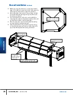
Figure 45:  Mounting Shroud Components

Corner extrusion

Mounting clip & 1/4-20 x 

 50 screw (P/N 41A1074)

Shroud panel

End cover 

support

End cover support P/N 

24B0982NN

“Inverted’ corner 

extrusion

Drive side end cover 

supports

Idler side end cover 

supports

3/8-16 X 3/4 Screw (P/N 

41A1072)

End cover support P/N 

24B0981NN

3/8-16 X 3/4 screw (P/N 

41A1072)

NOTE

Shroud install steps show install for a RH door. Install for 

a LH door is the same, but mirrored to the opposite side.

Summary of Contents for 209

Page 1: ...MANUAL PART 17A235 OWNER S MANUAL MODEL 209 Full Aluminum MODEL 209 Full Vision ...

Page 2: ... Lintel Seal 22 Shroud Installation 24 Electrical Startup 29 Controller Functions 32 Setting Door Limits 36 Warning Labels 37 Pair Transmitter Controller 38 MAINTENANCE 39 47 Cleaning Procedures 39 Preventative Maintenance 40 Preventative Schedules 41 Troubleshooting 42 Error Codes 43 REPLACEMENT PARTS 48 55 Instructions for Ordering 48 Door Identification 49 ID Tag Location 48 Left hand Face Fram...

Page 3: ...on which if not avoided could result in death or serious injury CAUTION indicates a potentially hazardous situation which if not avoided may result in minor or moderate injury CAUTION used without a safety alert symbol indicates a potentially hazardous situation which if not avoided may result in property damage NOTE explains general information DANGER indicates an imminently hazardous situation w...

Page 4: ...erly tagged and locked out during all mainte nance or service of equipment With the power supply disconnected always verify using a volt meter 7 All electrical troubleshooting or service must be completed by a qualified electrician or service person and must meet all applicable local state federal international and other governing agency codes 8 When it is necessary to service the control box with...

Page 5: ...the claim giving rise to such damages is based upon breach of warranty expressed or implied breach of contract tort strict liability or any other theory of liability even if a party has been advised of the possibility thereof and regardless of any advise or representation that may have been rendered by asi concerning the sale or use of the door system At ASI s request customer shall return to ASI ...

Page 6: ...gure 1 Shipping crates will contain the face frame assemblies the curtain and header assembly the shroud components the loose parts box and the control box For your protection note any damages or shortages on the carrier s bill of lading before signing the bill for receipt The installation of this door will require at least a two man crew and a fork lift Wider doors require 2 fork lifts Select for...

Page 7: ... your specific opening Before mounting any components check opening for width at top middle and bottom and check square of opening Check level of top of opening and plumb of sides Check mounting surfaces for any obstructions or surface irregularities Mounting surfaces should be free of debris and as flat as possible before mounting components Any deviations in the opening from the dimensions the d...

Page 8: ...king plates on the far side of wall are recommended 4 Measure and hold inside dimension between face frames at WIC plus zero minus 1 8 as shown Header mounts on the outside surfaces of the face frames so this dimension can t be oversize or the header will not fit properly Outside dimension is show for reference This dimension has to be less than the distance between header plates Face frame extrus...

Page 9: ...r surface 10 Check plumb of mounting surfaces of both face frames Add shims to low areas to keep face frames plumb and straight Areas of face frames at through bolt mounting holes need to be flush with wall or shimmed properly so the face frame doesn t distort when through bolts are tightened Distorting the face frame will prevent the face frame covers from mount ing correctly later 11 When face f...

Page 10: ...n the spreader bar hangers at the top of the face frames and the header will not be level if face frames are not level Use a laser level to insure tops of face frames are level If floor is not level mount 1st face frame on high side of opening and shim bottom of other face frame to keep them level with respect to each other Face frames get mounted first then the header assembly Face frame covers g...

Page 11: ... brackets located at the tops of the face frames Level forks and slowly move assembly towards wall Use helper to help you guide assembly into position with back of header assembly flat against wall figure 12 End plates of header should fit outside of outer surfaces of face frame extrusions 3 Slowly lower lifting frame header assembly until rear spreader bar of header fits into hanger brackets on f...

Page 12: ...ader to face frames 6 per side Tighten all 12 screws securely Use pry point slot to help align holes with threaded track in face frame extrusion if needed figure 13 5 Tighten top nuts on each face frame that were lefthand tight from previous step If you can t reach bottom nuts with curtain rolled up tighten the ones you can reach After curtain is unrolled in a later step you will check re tighten ...

Page 13: ...urtain to the halfway point 4 Check if the curtain chain links are true with the channel openings in both face frame extrusions figure 19 5 If curtain is not centered loosen the two adjustment bolts on the operator mounting bracket figure 20 Figure 19 Alignment Of Ends Of Curtain Into Face Frames Figure 20 Adjust Position Of Operator Curtain Assembly Figure 18 Manual Operation Pull Cords Red Manua...

Page 14: ...ll the way 10 Rotate torque tube until the adjustable link always on left side is accessible 11 Tighten or loosen nut on adjustable link to raise or lower left side of curtain until curtain is straight and true with face frame extrusions figures 21 22 12 With curtain in completely unrolled position check and tighten any nuts at tops of face frames that were left hand tight from previous install st...

Page 15: ...rame and out the top of the channel Wire these leads into the control system for photoeye control per the schematic for the door Light curtains or photo eyes can also be added to an existing door in the field If you are field installing light curtains or photo eyes install per figure 23 24 and wire them to the control system per the schematic for the door Channel Cover Leads from Light Curtains Ph...

Page 16: ...into vertical position and guide into position with mating face frame extrusion Rotate face frame cover into position from curtain side to outside as shown in figure 29 to insure that tab in cover extrusion seats into base extrusion properly Align holes in face frame cover with threaded slot in face frame extrusion 5 Hold in position and starting from bottom add fasteners p n 41a1029 to each hole ...

Page 17: ... the curtain completely lowered mount the spreader support gusset s packed in hardware bag in loose parts box to the center support s on the header frame figure 32 Doors will have 0 1 or 2 sets of stiffeners mounted on the header depending on the width of the open ing and whether or not the door was ordered with a shroud Install 1 spreader support gusset for each set of stiffeners on header Lift t...

Page 18: ...s in the header end plate and through the top rear spreader bar across to the drive side of door There should be a length of string routed through the top rear spreader bar to aid you in routing cables through it Tie the string to the cables to be routed and pull them through the spreader bar from the other side of the header Drive side face frame sen sor wires Routed through hole in top of header...

Page 19: ...ader end plate Route leads through center hole through center of top rear cross tube to drive side of door and down to control box Sensors In Idler Side Face Frame Cover Leads will come out of the top of the cover at the bottom of the header end plate Route lead through slot in lower rear corner of header end plate to the outside of the header end plate Route leads up to and through the center hol...

Page 20: ...s or photoeyes the control box and incoming power Figure 36 209 Electrical Routing Detail All wiring and connections are detailed on and must conform to the electrical schematic drawing that was shipped with your 209 door The electrical schematic drawing is specific to your door and any options chosen for your application NOTE 208v power requires the use of a boost box to convert the voltage from ...

Page 21: ...ASI DOORS INC 800 558 7068 asidoors com 21 Wiring Layout Continued INSTALLATION Figure 38 209 Electrical Routing Motor Connections Detail Figure 37 209 Electrical Routing Detail Side View ...

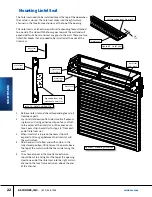
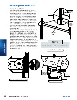
Page 22: ...ach to the center of the lintel slat on the concave sur face Foam strip should start stop 3 4 from each end of lintel seal slat 3 When lintel slat is in place the foam strip will expand to fill any gap between the lintel slat and the wall surface 4 After header is installed and with curtain in the fully closed position lift lintel seal to a point above the top of the curtain with the foam side fac...

Page 23: ...filler blocks with the smooth side towards the lintel seal the open end out towards the face frame extrusion and the hole to the top Insert the lintel seal filler blocks in the spac es between the ends of the lintel seal and the face of the curtain channels on both ends of the lintel seal 5 If the lintel seal is bowing out from the wall exces sively you can add a lintel seal clip to the top edge o...

Page 24: ...A1074 Shroud panel End cover support End cover support P N 24B0982NN Inverted corner extrusion Drive side end cover supports Idler side end cover supports 3 8 16 X 3 4 Screw P N 41A1072 End cover support P N 24B0981NN 3 8 16 X 3 4 screw P N 41A1072 NOTE Shroud install steps show install for a RH door Install for a LH door is the same but mirrored to the opposite side ...

Page 25: ...eader end plates for each cover Shroud panels will be cut with a 1 2 overlap on the idler side and a 7 1 4 overlap on the operator side Figure 46 Mounting Shroud Support S Figure 47 Mounting Clip Detail 1 Retrieve end cover supports from the loose parts box 2 Shorter supports get mounted on the idler side and longer supports are mounted on the drive side 3 Note that the 2 front end cover supports ...

Page 26: ...ner extrusion and attach it to the lower shroud support 5 Mount panel 2 P N 24B0979NV lower front panel Slide three mounting clips into the slot of the attached extrusion and with the extrusion on top align the end of panel 2 with the end of panel 1 on the idler side This panel and all the remaining panels have a strip of velcro that should line up with velcro installed on the spreader bar stiffen...

Page 27: ...41A1074 8 Mount panel 5 P N 24B0976NV top panel This panel does not have an attached extrusion and just slides into the slot on the extrusion on panel 4 Push into place to fully seat the panel into the slot in the extrusion keeping it aligned with the previous panels on the idler side fig ure 53 9 Install the end covers The header end plates have 4 end cover supports There is a velcro pad on each ...

Page 28: ...p is just outside of the shroud panels and push into position and the velcro pads will hold the end covers in place figure 55 13 After shroud panels are all installed protective coating on shroud panels should be removed 14 Score the protective coating on each panel by running a razor along the corner extrusions on both sides of the panel Peel off the protective coating and discard Velcro pads on ...

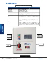
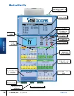
Page 29: ...wer applied horizontal position Power disconnected Locks Two locks help prevent unauthorized access to the controller Display Organic LED OLED display that provides the primary user interface Display is visible through the enclosure door Provides controller and door status indications during normal operation Provides programming and setup menus and provides error indications Table 01 Control Box D...

Page 30: ...ol Output Power Terminal Block Motor Connection Braking Resistor Connection Input Power Connections Mains Wiring Guide Exterior Button Connector Up Button Down Button Standard Inputs Configurable Inputs Terminal Block Output Relay Terminal Block RS 485 COM Terminal Block INSTALLATION Figure 57 Controller Features ...

Page 31: ...n certain menus While on an IDLE screen press to enter EXPRESS menu Exterior Button Connector Connects the ribbon cable from the OPEN STOP CLOSE switches on the enclosure door to the DGII DOWN button During programming and setup press to navigate through menus or to jog the door in the closed direction in certain menus Motor Connections Terminal blocks for connecting the motor are located on the b...

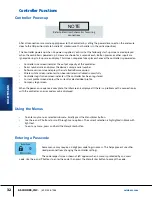
Page 32: ... board wireless initialized successfully Controller registration screen indicates if the controller has been registered Current profile screen displays the currently selected door profile Company logo screen When the power on sequence is complete the idle screen is displayed If there is a problem with a connection or with the controller an error code may be displayed Controller Power up To enter a...

Page 33: ...3 2 2 2 Figure 58 Menu Structure Figure 58 is a diagram showing the Controller menu structure The key presses to navigate through the main menus are also shown Menu Enter and To exit any menu press and hold the Menu Enter button Menu Structure 1 2 1 The table at the right refers to the numbers by each menu item Different menu items have different levels of security and higher level items require a...

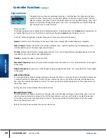
Page 34: ... voltage when selected This is useful for performing troubleshooting and is not intended for use as the normal operational display Position displays the door s current position Measured Frequency displays the measured frequency from the motor in hz This value correlates to the speed of the motor Output Frequency displays the current frequency being applied to the motor This value correlates to the...

Page 35: ...pen alarm timer in seconds and tenths of seconds To edit the time interval use the and buttons to select the desired value then press the menu enter button to store it The message stored is briefly displayed then the screen returns to the express menu Setting this value to zero disables the open alarm Run Timer Run timer value in seconds The run timer is a safety feature that stops door movement i...

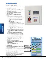
Page 36: ...down e Door is now ready to set the open limit Using the UP DOWN buttons jog door to the desired open limit f Press Menu Enter to complete open setting g Door is now ready to set the close limit Using the UP DOWN buttons jog door to the desired close limit h Press Menu Enter to complete close setting 8 Limit setup is now complete The controller should return back to the main menu if not press and ...

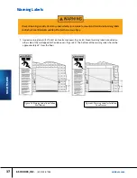
Page 37: ... side of the wall opposite the side covers Figure 62 The bottom of the warning label should be approximately 60 from the floor Figure 61 Warning Label Installation Face Frames Figure 62 Warning Label Installation Wall Mount Checkallwarningsweekly Doormayunexpectedlyclose Failuretomountandmaintainallwarninglabels andinstructionalliteraturecouldresultindeathorseriousinjury ...

Page 38: ...ring on controller press enter and within 10 seconds press the button on the transmitter 16 If the pairing is successful the controller will beep 17 Select the press and hold button to exit 18 Replace the wireless transmitter on the bottom bar assembly It is recommended that you mount it with the button against the bottom bar to prevent accidental un pairing The wireless transmitter and the contro...

Page 39: ...ls Never use aromatic or halogenated solvents like toluene benzene gasoline acetone or carbon tetrachloride on Acrylic polycarbonate materials Use of incompatible cleaning materials with Acrylic sheet can cause structural and or surface damage Contact with harsh solvents such as methyl ethyl ketone MEK or hydrochloric acid can result in surface degra dation and possible crazing of Acrylic sheet Ne...

Page 40: ...oor Lubrication and Cleaning Inspect Bearings and Locking Collars Inspect Operator Assembly Braking Inspection Inspect Curtain Connecting Links Table 03 Preventative Maintenance Table Remove power at the fused disconnect during all electrical or mechanical service Disconnect must be properly locked out during maintenance or service of equipment Failure to discon nect power could result in serious ...

Page 41: ... or drifts Slow stop and drift may require brake adjustment or replacement Brake air gap should be between 0 2 0 9 mm INSPECT CURTAIN CONNECTING LINKS Remove face frame covers and inspect curtain connecting links for signs of wear or damage Replace as needed DAILY VISUAL DAMAGE INSPECTION Visually inspect the door for any damage that may be present Example evidence of face frame impact damaged bot...

Page 42: ...ng and reverse 1 Loose or poor connection 1 Check connections in control circuit D Reversing edge works on opening cycle instead of closing 1 Phase sequence reversed 1 Shut off power Change any two of the three line leads E Door closes and opens 1 Reversing edge switch signalling to reopen 1 Check lower limit and shorten travel so door does not hit at bottom F Brake does not disengage or limits va...

Page 43: ...System Status DC link to check that the voltage is within the range shown Decrease the deceleration ramps OC1 Overcurrent 210 Medium Priority The motor current exceeds the inverter rating by 210 View the motor current display to check the current delivered to the motor Check the motor nameplate data to confirm that the correct controller model is being used Check for mechanical obstruction or dama...

Page 44: ...emperature display shows raw analog counts and not actual tempera ture Check ventilation and ensure fan if equipped is operating Reset the controller and confirm that the fan operates for 1 second during the power up routine Reduce the switching frequency and the DC brake level HE Low internal 12V Top Priority The internal 12VDC power supply voltage is too low View the System Status Int Levels to ...

Page 45: ...EV E03 No Signal From Pulse Generator occurs during setup only Low Priority No pulse input detected from the encoder Check door for obstruction Ensure the pulse output from the encoder is connected to terminal P2 on the Controller Verify that the encoder pulse output is set correctly E04 N A N A N A E05 Reference Switch Connection Medium Priority The reference switch is shorted or broken Check the...

Page 46: ...ion in door s path E11 Safety Edge 2 Activated Low Priority The reversing edge has been activated Check for obstruction in door s path E12 Lifting Force Exceeded Low Priority The torque limit has been exceeded If the torque limiting feature is being used adjust the torque limit parameter to suit the application E13 N A N A N A E14 Absolute Encoder Comm Loss Top Priority Communication with the abso...

Page 47: ...bled then power cycle the controller E20 N A N A N A E21 Option SeyWave OCS Remote Timeout A paired SeyWave wireless O C S remote has timed out Check the remote for operation Refer to supplied SeyWave wireless manual for troubleshooting E22 Option SeyWave DS Remote Timeout A paired SeyWave wireless door sensor remote has timed out Option SeyWave DS connection fault E23 Option SeyWave DS Connection...

Page 48: ...doors reserves the right to discontinue any part and make design changes without notice Refer to the information tag on your door and record the 1 Door model number 2 Job number 3 Door number 4 Manufacturing date Use part numbers referenced in this manual If the item is not found in the manual the product code on the back of the item is helpful If your door has no information label the approximate...

Page 49: ...Determining the Job Number Model and Year of Manufacture of your door is necessary to provide quick and accurate parts identification The following is a description of labels and their locations When ordering parts specify Job Number Door Number and Manufacture Date Figure 67 Label Location Figure 66 ASI Door Label ASI Doors ID Tag REPLACEMENT PARTS ...

Page 50: ...7 13 AR EXTRUSION PHOTO EYE TRACK 44B0047NV 14 ASM SIDE FRM CVR LH NO LIGHT CURTAIN 76B0057LV ASM SIDE FRM CVR LH W LIGHT CURTAIN 76B0058LV 1 EXTRUSION COVER VERTICAL COLUMN 44B0055 5 1 WEAR STRIP COVER 209 HIC 11B0314 6 1 SLAT GUIDE WEDGE 14B0311NN 7 AR ASM LIGHT CURTAIN RECEIVER 24B0815 8 AR ASM LIGHT CURTAIN TRANSMITTER 24B0816 9 AR EXTRUSION PHOTO EYE TRACK 44B0047NV 14 AR FILLER PHOTO EYE TRA...

Page 51: ...4 T 10 AR PHOTOEYE RECEIVER 23B0124 R 11 AR HEX M3 X 0 5 MM SS 41A1026 12 AR M3 X 0 05MM X 16MM BH HD SS 41A1027 13 AR EXTRUSION PHOTO EYE TRACK 44B0047NV 14 ASM SIDE FRM CVR RH NO LIGHT CURTAIN 76B0057RV ASM SIDE FRM CVR RH W LIGHT CURTAIN 76B0058RV 1 EXTRUSION COVER VERTICAL COLUMN 44B0055 5 1 WEAR STRIP COVER 209 HIC 11B0314 6 1 SLAT GUIDE WEDGE 14B0311NN 7 AR ASM LIGHT CURTAIN RECEIVER 24B0815...

Page 52: ...R 1 50 DRIVE RH 1 1 81B0016LV ASM HEADER 2 0 DRIVE LH 1 1 81B0016RV ASM HEADER 2 0 DRIVE RH 1 1 24B0966LV ASM TORQUE TUBE LH 1 5 DRIVE 2 1 24B0966RV ASM TORQUE TUBE RH 1 5 DRIVE 2 1 24B0953LV ASM TORQUE TUBE LH 2 DRIVE 2 1 24B0953RV ASM TORQUE TUBE RH 2 DRIVE 2 2 2 2 2 24B0952NN ASM CAM FOLLOWER 3 1 2 3 Torque tube assemblies are sub components of the header assemblies listed and are listed for re...

Page 53: ...UE 50A0216 F2 1 AR AR GEARMOTOR 2 BORE 230V LOW TORQUE 50A0216 F3 1 AR AR GEARMOTOR 2 BORE 460V LOW TORQUE 50A0216 F4 1 1 ASM ENCODER RH DRV APEX 24B0792F2 2 1 ASM ENCODER LH DRV APEX 24B0792F1 2 1 ASM ENCODER RH DRV APEX 24B0792F2 2 1 ASM ENCODER LH DRV APEX 24B0792F1 2 1 1 SPROCKET 40 TEETH 40 CHAIN 1 1 2 BORE 50A220 3 1 1 SPROCKET 40 TEETH 40 CHAIN 2 BORE 50A219 3 1 1 KEYSTOCK 375 X 375 X 6 00 ...

Page 54: ...ASI DOORS INC 800 558 7068 asidoors com 54 Curtain Assembly 9 3 15 2 4 16 14 12 13 10 5 1 5 3 9 9 10 REPLACEMENT PARTS ...

Page 55: ...END CAP BOTTOM BAR MACHINED 14B0324NN 8 AR SEAL SLAT HINGE 15B0062 9 1 EXTRUSION LIVE EDGE ADAPTER WIC 3 03 11B0147 10 1 TRANSMITTER EDGE SENSOR WIRELESS 23B154 11 1 SENSING EDGE 15 25 TTLi PROFILE WIC 1 53 23B156 12 1 END CAP W 0 5 METER CABLE 23B157 13 1 END CAP W 8 2 ohm RESISTER 23B158 14 1 ASSEMBLY ENDCAP LINK PLUG WHEEL 24B0936 15 1 GASKET 1 0 GREY VINYL 15A009 16 4 WASHER FLAT 8 41A078 17 4...

Page 56: ...anual for the 209 apex dura vision doors All warranties safety practices and warning descriptions pertaining to this door can be found in on page xx and apply to procedures and instructions contained in this bulletin Hybrid and Adjustable Link Assembly Replacement ...

Page 57: ...being restored to the door while you are working on it The adjustable link assembly is always on the left and the hybrid link assembly is always on the right regardless of which side the operator is on If you are replacing the idler side link assembly only you do not have to move the barrel out If you are replacing the drive side link assembly or both assemblies you do need to move the barrel out ...

Page 58: ...ide of the header Remove the fasteners holding the hybrid link assembly on right side of header to the slat wheel 2 Temporarily use a piece of tape to hold the hybrid link assembly against the wall and away from the barrel assembly Unattach Existing Adjustable Link Assembly From Slat Wheel Unattach Existing Hybrid Link Assembly From Slat Wheel Remove adjustable link from slat wheel on left side of...

Page 59: ...ine with one of the ribs on the motor casting to make it easy to see when they are lined up 3 Use the chain drive to rotate the barrel assembly moving the barrel out away from the wall exactly three complete revolutions Make sure you are moving barrel assembly OUT not IN Manually Rotate Barrel Assembly Manual operation pull cords Figure 7 Manual Operation Controls Manual operation drive chain Figu...

Page 60: ...of header Hybrid Link Assembly side Figure 8 Top Link Of Curtain Right Side Of Header Left side of Header 1 Referring to figure 9 note position of the attachment hole on the top link of curtain on the left side of header Measure position of this hole from the bottom of the header plate and from the wall surface 2 From outside of header on left side drill a hole through the header end plate that li...

Page 61: ...ee figure 10 from the curtain assembly 2 Use the access hole you made and remove the shoulder screw holding the adjustable link assembly 3 full links half link 2 adjusting brackets to the top slat link on the curtain 1 Remove the hybrid link assembly 24B0935NN see figure 11 from the curtain assembly 2 Use the access hole you made and remove the shoulder screw holding the hybrid link assembly 3 ful...

Page 62: ...rilled through header in last step to attach the new adjustable link assembly to the top link of the curtain on the left side of the header Use a 5 16 x 3 4 shoulder screw P N 41A1056 to join the links Shoulder screw must be greased with a silicone lubricant 2 Temporarily use a piece of tape to hold the adjustable link assembly against the wall and away from the barrel assembly until it is moved b...

Page 63: ...hex nut P N 41A639 Attach adjustable link to the slat wheel on left side of header Figure 15 Attach Adjustable Link Assembly To Slat Wheel 1 Attach the hybrid link assembly P N 24B0935NN see fig ure 17 18 to the slat wheel 2 Use the following hardware to attach the adjustable link assembly to the slat wheel 5 16 x 3 4 shoulder screw P N 41A1056 Attach hybrid link to slat wheel on right side of hea...

Page 64: ...l warranties safety practices and warning descriptions pertaining to this door can be found in the original owner s manual and apply to procedures and instructions contained in this bulletin Please refer to the original owner s manual for that information Reversing Edge and Wireless Transmitter Replacement ...

Page 65: ...e the disconnect lever on the control to disconnect power to the door Use proper Lock out Tag out procedures to prevent power being restored to the door while you are working on it Before You Start Side Frame Extrusion Covers Figure 1 Remove Side Frame Covers Figure 2 Block Curtain Block curtain for easier access to components 1 If you are only replacing the wireless transmitter skip this section ...

Page 66: ...the other end of gasket to remove gasket 2 Support the bottom bar assembly from below and remove the screws holding it to the slat above it Loosen and remove the 5 16 x 3 4 shoulder screws 41a1056 in endcap links from both ends of slat figure 4 3 Remove entire slat assembly and lay on a work surface with the transmitter facing up Figure 3 Remove Hinge Gasket 5 16 x 3 4 Shoulder Screws 41A1056 Figu...

Page 67: ...dge skip to the reversing edge section do steps 1 12 return here to prep the new transmitter 6 Prepare the new transmitter for install The transmitter has 3 wires black blue and white The white wire is not used and should be cut off if it isn t already Strip the ends of the black blue wires for connection 7 To be able to make connections you may need to pull the wire nuts off the tape that is hold...

Page 68: ... top that slides into a slot in the extrusion above it in the bottom bar Figure 7 Pull the reversing edge sensor out of the slot in the extrusion horizontally 4 Orient the new reversing edge s wires to be on the same end of bottom bar as the transmitter was mounted on 5 The reversing edge with the caps installed on the ends should be the same length as the slat 6 Slide the new reversing edge senso...

Page 69: ...e transmitter 4 Fit the wires back into the cavity of the bottom bar and put the wire nuts back into the access hole where they were 5 Route the wires from the reversing edge into the channel cut in the end cap link 14B0324NN you removed earlier Figure 9 Position the end cap link back on the slat keeping the wires in the channel replace the 2 1 4 20 X 2 00 screws 41A1070 and tighten 6 If you also ...

Page 70: ...e button on the transmitter 15 If the pairing is successful the controller will beep 16 Select the Press and Hold button to exit 17 Replace the wireless transmitter on the bottom bar assembly It is recommended that you mount it with the button against the bottom bar to prevent accidental un pairing The wireless transmitter and the controller are paired together at the factory They need to be paire...

Page 71: ...h One way to avoid this is to work from the center out 5 Find center of the slat and the center of the hinge gasket Start installing hinge gasket from the cen ter of the slat and work towards the ends in both directions Starting at the center of slat push the triangular ribs of the gasket into the small chan nels of the slat extrusions being careful to guide the gasket rib between the slats Figure...

Page 72: ... Also the gasket will stretch and pull while working in one direction so you need to take care to make sure the gasket will cover the slat to the end on both sides 9 You should have some extra gasket hanging over ends of slat on both sides Trim gasket to the ends of slat and fully seat end of gasket into channel 10 Check and re tighten any screws on endcap links loosened in previous steps 11 Repla...

Page 73: ...on doors All warranties safety practices and warning descriptions pertaining to this door can be found in the original owner s manual and apply to procedures and instructions contained in this bulletin Please refer to the original owner s manual for that information Slat Hinge Gasket Replacement ...

Page 74: ...face frame covers Pull off face frame covers and set covers screws aside Figure 1 4 Place wood or foam blocks between curtain and face frame extrusion close to damaged slat s This will allow curtain to hang in front of face frame extrusion to allow you to get better access to the slat mounting screws and make it easier to remove the slat s Figure 2 The following are instructions to remove damaged ...

Page 75: ...slat s need to be removed 6 Pry up one end of gasket Grip gasket end and pull at an angle from face of slat all the way to the other end of gasket to remove gasket 7 On slat s to be replaced loosen and remove two 20 screws in end cap links from both ends of slat s Figure 4 Figure 3 Remove Hinge Gaskets Pry up end of hinge gaskets and pull out to remove Remove 1 4 20 Screws Endcap Link Figure 4 Rem...

Page 76: ...ets Continued 1 Remove slat by pushing slat straight out from behind Figure 5 If slat is too tight to remove loosen but do not remove screws on endcap links of slats above and below slat to be removed Be sure to re tighten these screws after replacing slat s Figure 5 Remove Slat ...

Page 77: ... slats in curtain with the slat facing the same way as the other slats in the curtain 2 Push slat into position Looking from end of curtain towards endcap link align screw channels in slat extrusion with holes in end cap link 3 Replace 20 screws and tighten Tighten 20 screws on adjacent slats above and below if they were loosened in removing slat Repeat on other side Figure 6 Slat and Endcap Link ...

Page 78: ...en the slats Figure 10 6 Using a putty knife as mentioned to guide the rib into position apply pressure with your thumb to push against the concave surface of the gasket Slide along the gasket for a short distance 12 or so Switch sides and work from center in the opposite direction roughly the same distance until the center 2 ft Or so of the gasket is seated 7 Care must be taken the ensure that th...

Page 79: ...asidoors com ASI DOORS INC 5848 North 95th Court Milwaukee WI 53225 800 558 7068 ...

Reviews: