Installation
Installation Kit Included (find in carton)
2
www.americanspecialties.com
1. Make sure power supply breaker is switched off. Installation must be carried out in accordance with
the current edition of the local wiring regulations code having jurisdiction. Installation should be
performed only by a qualified electrician.
2. Place template against wall at desired height (see mounting height recommendations) and mark
locations of 4 mounting holes and wire service entry at knockout (KO) location.
Note:
For two or more dryers, dryers should be no closer than 24 inches (610 mm) on center.
3. Remove and retain 2 cover screws and cover.
4. a.
For in-wall (concealed) power supply - (See MT & IG 1207101509)
Provide supply wire to KO location according to local code and attach securely to chassis at KO
with appropriate strain relief connector (not supplied).
b.
For Surface Mounted Conduit (exposed) power supply -
Provide appropriate conduit to entry location according to local code and attach securely to chassis
with correct strain relief connector (not supplied).
5. Drill four (4) holes at locations A, B, C and D of Ø5/16" (Ø8) Diameter x 1-3/8" (35mm) deep if using
wall anchors supplied with unit. Install supplied anchors flush with wall face, or install other fastening
system suitable for wall conditions (not supplied). Attach dryer to wall. For wood wall/studs use Ø1/4
inch (M6) screws at length that will ensure 1 inch (25 mm) min. stud penetration. For masonry walls
use expansion bolts or anchors for Ø1/4 inch (M6) screws to ensure penetration 1/4 inch (6 mm)
deeper than anchor. Shim if necessary to ensure base plate is flat against wall.
6. Connect supply and ground wires to terminal block where indicated or connect supply wires to
terminal block where indicated and connect ground wire to base plate with ground screw.
Connections:
A
. Connect the live wire (colored Brown, Red or Black) to the terminal block marked "L".
B
. Connect the neutral wire (colored Black, Blue, White or Grey) or connect the second live wire
(colored Red or Orange) to the terminal block marked "N".
C
. Connect the ground wire to the terminal block marked " " or to the green screw marked " ".
Bare grounding (earth) wires should be sleeved with green and yellow or green tubing.
Colors of live and neutral wires depend on voltage of supply service and requirements of Building
and Electrical Code having jurisdiction.
7. Replace cover. Do not over-tighten screws.
Service Tool Included (with installation kit)
Security hex driver 4 mm x 1 pcs (5/32" pin-hex will work if tool is lost)
Please unpack the unit and check the quantity of the above tool and kit.
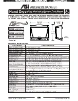
Operating Instructions and Parts Manual
Hand Dryer
Surface-mounted
ADA
-compliant hand dr yer
VAC
110
115
120
208
220
230
240
277
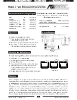
Motor
Heater
Vac
110
115
120
208
220
230
240
240
Inrush A(W)
5.73 (630)
5.99 (689)
6.25 (750)
2.71 (563)
2.86 (630)
2.99 (689)
3.13 (750)
3.13 (750)
Operating A (W)
3.82 (420)
3.99 (459)
4.17 (500)
1.81 (376)
1.91 (420)
2.00 (459)
2.08 (500)
2.08 (500)
3.82 (420)
3.99 (459)
4.17 (500)
1.81 (376)
1.91 (420)
2.00 (459)
2.08 (500)
2.08 (500)
Vac
110
115
120
208
220
230
240
240
Total
Inrush A(W)
9.55 (1050)
9.98 (1148)
10.42 (1250)
4.51 (939)
4.77 (1050)
4.99 (1148)
5.21 (1250)
5.21 (1250)
Operating A(W)
7.64 (840)
7.99 (918)
8.33 (1000)
3.61 (751)
3.82 (840)
3.99 (918)
4.17 (1000)
4.17 (1000)
№
0199-1
0199-1
0199-1
0199-2
0199-2
0199-2
0199-2
0199-3
Model
Input
Inrush / Operating A(W)
1. Self-Threading screws 1/4" x 1-1/2" (M6 x 38) x 4 pcs 4. Crimp-on terminal wire tip x 3 pcs
2. Metal Washer 3/8" x 7/8"x 1/16" (Ø10 x Ø22 x 1.6 thk) x 4 pcs
3. Nylon bushing x 4 pcs
5. Plastic anchor Ø5/16" x 1-3/8"
(Ø8 x 35) x 4 pcs
1207131423 Rev C 3 October. 2013
distributed by
RESTROOM DIRECT 704 . 937. 2673
www.
RestroomDirect
.com

