2022/03/16 04:45
13/18
MS2000, MFC2000 and RM2000 OPERATION
Applied Scientific Instrumentation - https://asiimaging.com/docs/
persistent using the “SS Z” command, which saves all parameter settings to nonvolatile flash
memory. Users wishing to make a one-time permanent change to a parameter setting can use a
terminal program to communicate with the controller, make the parameter change, and then make
the change persistent with the “SS Z” command. The new parameters will be used on subsequent
power down/up or controller RESET. The user can restore the Factory Default parameter settings any
time using the serial command “SS X”.
Saved Stage Positions, Limit and Home Positions
The controller watches the power line voltage so that it can detect when the controller is being turned
off. There is sufficient stored charge in the controller’s power supply to allow the controller to save the
stage position and a few other variables as power is being shut down. The variables that are saved
are the Stage Axis positions, the programmable Upper and Lower limit locations, and the Home
location all expressed in the current coordinated reference system. When power is restored, the
controller loads the saved information into its working memory and clears the data from the Saved
Position nonvolatile memory locations to ready those storage locations for when power is again shut
off.
If the controller is RESET (without turning off the power)
current locations are NOT saved, and the controller will come
up with axis positions at zero and default Limit and Home
positions; the Saved Position information will be lost.
Successful shutdown is indicated by “OK” broadcast on the serial port upon power-off.
Internal I/O connector details
Special user requirements often require custom external wiring. The MS 2000 WK controller has an
internal board connector with several I/O lines that are often wired to the external BNC connectors for
user connections. There may be occasions where the functions required are not wired to external
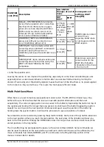
connectors. The table below shows the connector wiring and the firmware modules that are required
to take advantage of the I/O functions. The BU X command will list which modules are present in the
loaded firmware. On most controllers the IN BNC is connected to TTL IN0.
EXT I/O – SV1
PIN DESCRIPTION FUNCTION
FIRMWARE Modules
1
TTL IN0
INPUT-TTL input w/
processor interrupt (Usually
wired to the IN BNC)
IN0_INT used for external TTL triggered tasks – see
TTL command for specific functions.
ENC_INT use to count encoder pulses (selected
with JP2) in conjunction with SCAN firmware.
TTL_REPORT_INT used for triggered position
reporting.


