Last update: 2021/12/20 16:41
ms2000_operation
https://asiimaging.com/docs/ms2000_operation
https://asiimaging.com/docs/
Printed on 2022/03/16 04:45
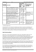
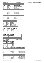
Status
Letter
Meaning
Column Priority Comments
D
Disabled / Disengaged 19
highest
Axis is disabled if run-away error condition is
detected
L
Lower Limit Engaged
19
mid
U
Upper Limit Engaged
19
mid
s
Slow Joystick Control
19
lower
f
Fast Joystick Control
19
lower
E
Clutch Engaged
19
lowest
Microscope Z-drive only
P
Axis in PAUSE state
20
highest Axis is BUSY while paused.
B
Axis BUSY
20
high
M
Motor Active
20
mid
Servos are turned on.
W
Command Wheel
20
lowest
Used on controllers where the command
wheel may be switched between axes with
the ‘@’ button.
The status indicators can help you understand how the controller is set up and working. The f, s, & W
indicators tell you which axes are being controlled by the manual control devices as well as the speed
range for the devices. Momentarily depressing the joystick button will switch the speed indicator from
‘s’ to ‘f’ or vise versa.
Should the stage be moved into either a hardware or software limit switch, the ‘U’ or ‘L’ indicators will
appear. Further movement into the limit is prohibited.
When a commanded move is issued to an axis via a computer command, the ‘B’ indicator will appear
until the axis reaches target to the accuracy specified by the PC error variable. Should the stage drift
further from the current target by more than the E drift error variable, the motors will re-engage and
the ‘M’ will appear as the right status indicator. The ‘M’ will disappear when the stage is again within
the PC error variable of the target. When using manual input devices (joystick or knob), the ‘M’ will
appear as the motors attempt to keep the XY stage and Z drive at the location specified by the input
devices.
If excessive servo errors are encountered, the axis will be disabled and the ‘D’ will appear. This is a
safety feature to limit motion under run-away conditions or in the event of a stage crash.
Back Panel
USB Port
To use the USB port, you need to install the necessary drivers onto your computer, they are available
for download from
. Please note that the Windows 10 Universal drivers do not
work with ASI controllers; if you are running with Windows 10 OS, use the drivers for Windows 7/8/8.1.
After the drivers are installed, you can check the communication between your computer and the
controller by using your computer’s Device Manager. Before you connect and power up your ASI
controller, expand the “Ports (COM & LPT)” menu
and note any communications ports listed.
Connect the controller via the provided null modem cable. When you power up the connected
controller, you should see a new communications port listed. (For example, if you see COM1 before


