Last update: 2021/12/20 16:41
ms2000_operation
https://asiimaging.com/docs/ms2000_operation
https://asiimaging.com/docs/
Printed on 2022/03/16 04:45
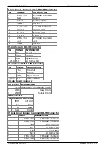
IN0_INT †
TTL IN0 used for a variety of interrupt driven functions selected using the
TTL command.
† These modules are often included in standard builds. If you see something you want but don’t have,
contact ASI.
Power Down Coordinate Save
Beginning with firmware version 8.1, powering down the MS 2000 controller will automatically cause
the current positions to be saved to non-volatile memory so they can be restored upon startup. The
shutdown procedure watches for power failure and immediately turns off the motor drivers before
saving the position coordinates. Any power interruption will shut down operation. The user can always
reset the stage coordinate origin using the ZERO button, however the actual position of the preset
firmware limits remain unchanged with this operation. To reset the controller with default firmware
limits and with zero stage coordinates, press the RESET button on the back of the controller. With the
RESET operation, the current stage position will be lost. Upon loss of power, the controller will send
the character ‘O’ out the serial port. After successfully saving positions, the controller will send the
character ‘K’.
Save Settings to Non-Volatile Memory
The MS 2000 controller allows the user to customize various parameter settings and then save the
settings to non-volatile memory to be used on subsequent power-ups. The controller is shipped with
general purpose default setting suitable for most users. The user can always return to the default
settings unsuitable parameters are saved. See the
the manual.
Post-Move Control Options
The behavior of the stage and controller at the completion of a move can be controlled with several
programmable parameters. The best method can depend upon the particular application, the thermal
and vibration environment, whether linear encoders are used, speed required, etc. The various
options are set using the
codes for each axis. The Finish Error and Drift
Error tolerances are set with the
and
command can
be used to enter a PAUSE state or control the motor drivers following a move. The table below shows
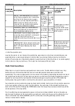
how the various command options can be used.


