background image

Attach the microscope analogue to the incident 

ht stand on the column of the T/I base , fas-

n it with the knurled screw and secure it with 

lig
te
the clamp ring. 


Picture 22: Base for transmitted or incident 
light (T/I) 

nt side. The push switch allows the 

hoice between transmitted or incident light. 

rightness 

f the corresponding illumination equipment is 
ossible with the control unit on the left front 

s unit if investigations in 

ixed light are necessary. 

he T/I base. 

 
Switch on the T/I base with a pressure switch 
on the fro
c
For this, an incident light illuminator must be 
assembled to the microscope and has to be 
connected to the right power source.


An infinitely variable alteration of the b
o
p
side of the T/I base. 
 
The incident light equipment can be connected 
to an additional serie
m
 
Focus the transmitted light illuminator by push-
ing the bar on the back of t


22 

Summary of Contents for SMC 4

Page 1: ...Stereo Microscope SMT 4 Stereo Zoom Microscope SMC 4 User Manual ...

Page 2: ...anging the attachment lenses 12 2 3 6 Changing the eyepieces 12 2 3 7 Delivery option 12 3 Maintenance and Service 3 1 Changing the illumination 13 3 1 1 LED Illumination 13 3 1 2 Base for transmitted or incident light 13 3 1 3 Transmitted light Dark field device 13 3 1 4 Cold light illuminator 13 3 2 Changing the fuse 13 3 2 1 Transformator 13 3 2 2 Base for transmitted or incident light 13 3 2 3...

Page 3: ...zation 19 4 9 1 Polarizer 19 4 9 2 Analyser 19 4 10 Transmitted light polarization 20 4 10 1 Polarizer 20 4 10 2 Analyser 20 4 11 Incident light fluorescence equipment 20 4 11 1 Excitation filter 20 4 11 2 Blocking filter 20 4 11 3 Usage of a cold light device 20 4 12 Transmitted light Dark field device 21 4 13 Transmitted light base 21 4 14 Base for transmitted and incident light 21 5 Measuring i...

Page 4: ... 27 9 Stages and stands 9 1 Incident light stand Large stand 28 9 2 Column stand Universal stand 28 9 3 Turntable 29 9 4 Spherical stage 29 9 5 Gliding stage 29 9 6 Measuring stage 50 x 50 30 9 7 Mechanical stage 80 x 80 30 9 8 Mechanical stage K 150 and K 200 31 9 8 1 Assembly 31 9 8 2 Handling 31 10 Complaints Warranty 32 4 ...

Page 5: ...angerous voltage The unit must be disconnected from power be fore it can be opened for adjustments re placements servicing or repairs Existing ventilation slits should not be ob structed This also applies for ventilation slits on the bottom of the unit No tools loose objects or liquids should enter the unit through ventila tion slits or other openings in the unit Only fuses with the required nomin...

Page 6: ...ir is inserted The eyepieces braces of the binocular eyepiece can be swivelled in order to fit them to the individual optic distance of the observer and are equipped with dioptre rings for com pensating the individual accommodation and ametropia The corresponding eyepieces are inserted in them The drive is located at the backside of the mi croscope body The whole microscope can be clamped with a s...

Page 7: ...This enables the installation of an enlargement changer in form of a pancrat Two separate pictures are designed in the tube system which are arranged in every path of rays behind the enlargement changer and are observed with two separate eyepieces One mirror system for the obtainment of vertical and horizontal pictures and one for the deviation of the path of rays at 45 is lying between the tube s...

Page 8: ...h eyepiece 2 Eyepiece cone with dioptre rings 3 Tube 45 4 Middle part of the microscope 5 Luminance ring rotatable 6 Objective 7 3W LED incident light illuminator 8 Stand base 9 Holder for column 10 Drive mechanism 11 Column A built in zoom objective allows an alteration of the enlargement with factor 10 1 without a change of the eyepieces or of the objectives Various easily exchangeable adapters ...

Page 9: ... mi croscope 4 from the packaging this part has to be assembled directly at the column 11 Fix it with help of the screw on the backside of the drive mechanism 10 The objective 6 is screwed onto the center of the middle part of the microscope Please do not touch the surfaces of the optical parts of the GF Planachromat Before the tube 45 3 can be assembled to the middle part of the microscope all ot...

Page 10: ...hoose the lowest magni fication factor and try to adjust the sharpness by rotating the dedicated dioptre ring Please note You don t need to change the drive knob After the microscope has been set the object being viewed will be sharply portrayed at all levels of enlargement In case there are objects with different high then it is only necessary to focus the object again by changing the drive at hi...

Page 11: ... the knurled knob with help of a wrench For this the wrench has to be inserted into the adjacent hole beside the set screw The set screw can be tightened again if you have reached the stiff motion you would like to have Picture 3 1 Picture 3 1 Adjustment of the stiff motion of the drive with coaxial gross and fine drive coarse drive How to adjust the fine drive Please remove the cap at the left fi...

Page 12: ... necessary the tube can also be attached when turned at 180 The same use of two or more intermediate tubes is also possible but it depends from the used eyepieces and the used magnification factor Light shadowing might be on the edge of the field of view only appears during investigations that are exe cuted at factor 0 32x or with eyepieces PW 6 3x 25 or GF PW 10x 25 2 3 5 An exchange of all suppl...

Page 13: ...n to change the lamps Remove and rotate the ground plate and exchange the old halogen lamp against a new halogen lamp 6V 10W Subsequently mount the transmitted light dark field device in the re verse order Before you use the microscope the first time and after each change of the illumination the bulb has to be recentered again To do that you have to take a sheet of paper or a frosted glass Put it ...

Page 14: ...of middle consistency for lubri cating the slide faces of the gliding stage Lightly lubricate both faces in regular time in tervals with this grease Before doing this carefully remove the old grease with a grease dissolver 3 3 4 Eyepieces and attachment lenses should be cleaned regularly with a soft hair brush In addition these parts should be re moved from the equipment and all accessible optical...

Page 15: ...able 4 2 2 The Tilting eyepiece tube 2x Multi function tube offers a fatigue proof working in a lower and effortless increased attitude to work With the viewing angle of 10 to 55 you will get a variability in high of 45mm By rotating the braces of the eyepieces you will get a variability in high of 50mm As result you have a viewing high of 90mm as difference Picture 4 Tilting eyepiece tube 2x Mult...

Page 16: ... LED ring light illumination will be used for different working distances in combination with or without attachment lenses The characteristic of this kind of illumination is a uniform shadow free illumination of objects in all directions The assembly will be done with a special adapter The adapter has to screw directly onto the objective of the microscope The power connection will be over the buil...

Page 17: ...llowing filters are available and may be directly placed in front of the Semi fixed light guide Picture 10 Semi fixed light guide with focus sing attachment 4 6 2 For a uniform shadow free illumina tion of objects the semi fixed light guide or the flexible light guide can be substituted by a ring light illuminator four point ring illuminator or split ring illuminator that is attached in front of t...

Page 18: ...ors the brightfield is only a cross shaped range within the field of vision When other equipment of the SMT 4 SMC 4 is used the size of the lit field varies depending upon the used eyepieces and objectives 4 8 1 The use of a cold light device is rec ommended for challenging illuminations tasks which depend on a high and constant illumina tion strength as well as a specimen gentle vari able type of...

Page 19: ...ion the polarization filter can be mounted directly on the focussing attachment of the semi fixed light guide Picture 15 Polarizer 9 2 There are several variants for the ana A rotating analyzer is set in front of the 4 lyzer I objective and is fastened with a knurled screw Picture 16 Rotatable Analyzer A filter pusher formed like an intermediate II tube includes two parallel aligned polarization f...

Page 20: ...escent investigations The excitation filters in the lug in socket can be exchanged To do this lter usher formed like an intermediate tube The 4 the filter pusher align it to the darkening while looking through the binocular tube and fasten it with both screws Alignment is meaningless when using the analyser set in front of the ob jective since the analyser is rotatable and can 4 11 Incident Light ...

Page 21: ... base The frosted side of the mirror must be turned towards the light Correct the mirror po sition by turning the left or right adjusting knob while looking through the microscope and ad just the light field size by focusing the light Please note The image has the most contrast if the light field size is the same as the field of vi on is required for mixed light The light for cident light illumina...

Page 22: ...ion equipment is ossible with the control unit on the left front s unit if investigations in ixed light are necessary he T I base Switch on the T I base with a pressure switch on the fro c For this an incident light illuminator must be assembled to the microscope and has to be connected to the right power source An infinitely variable alteration of the b o p side of the T I base The incident light...

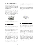
Page 23: ... bjects can be captured with a video or photo a irectly on a micro ope These captured objects can be stored in to quip a computer with digital camera like a f e software the manual is not part of this 5 T bratio of the measuring softw a urements The division is on the top side of the plate For calibrating the division is turned to the objective For direct linear measurement of even objects these a...

Page 24: ...table eyepiece a cross line p je suppress the individual accommodation The trinocular tube will be assembled between the middle part of the microscope and th o at the rear exit The camera objective has to be disassembled and instead of the objective the T2 adapter has to be placed The photo adjustment cannot be adjusted be cause it is so balanced that afte a appears sharp on the film level 6 S nec...

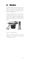
Page 25: ... to take a photo of the object The sliding objective al lows distortion free photos Stereoscopic investigations th you will notice a detent The sliding objective can be moved to the left or to the right so that the left or right light beam can be used to take photos icture 27 Sliding objective ective can be as mbled only in the factory A later assembly P Please note The sliding obj se isn t possib...

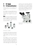
Page 26: ...ve a lamped with two screws The lower art will be set directly on the trinocular exit All TV adapter will be aligned factory made at the delivery In normal ca c clear picture you have to follow the instructions below The TV adapter 1x comes in two parts which will be c p the upper part will be set on the thread of the camera in most cases the thread comes as c mount Both parts will be add together...

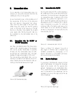
Page 27: ...sired observation angle icture 30 Intermediate tubes 2 Intermediate tube 50 50 he trinocular tube 50 50 is placed between P 8 T the middle part of the microscope and the bin ocular tube The trinocular tube is designed like an intermediate tube It defracts 50 of the light from every path of the light beam in or der to utilize this light for other purposes e g photography and TV Parallel to this a s...

Page 28: ...sal stand he Column stand is suited for investigations s a working radius of maximum 280 is equipped with a stable round base or a security ring a wrench and an articulated arning LED transmitted light illumination and built in power supply 9 T and observations of large surface bulky ob jects It allow mm and a working high of maximum 570 mm It stage clamp for holding stage leaves of 18 50 mm thick...

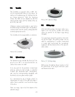
Page 29: ...stage 9 T jects at up to 20 in an optional direction as well as their rotation at 360 It stand as well as on the T I base is suited for incident and transmitted light investigations and must be correspondingly equipped with the black white or glass insertion plate It compensate the high of the spherical stage it self so that is possible to use the whole range of the drive T Picture 36 Spherical st...

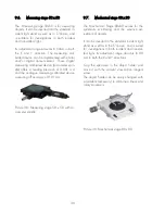
Page 30: ...ing calibrated device a reading off accuracy of 0 01 mm Picture 38 Measuring stage 50 x 50 with mi rometer spindle 7 Mechanical stage 80 x 80 ec s for the stematic scrutinizing and the sensitive ad the standard incident light and as well as in the T I base and is suited holder and ove it with the coaxial slow motion tangent le accessory to combine a linear and c 9 The M hanical Stage 80x80 serve s...

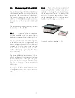
Page 31: ...or incident light investigations and can be used only with a special incident light base The stan to 9 b the base for transmitted and incident light T I The base for transmitted and incident light has to the column has to dismounted The column will mounted on the mike boom Now the mike boom has to be mounted with 3 screws on the mechanical stage the glass plate has to be removed before The pre ass...

Page 32: ...e conditions The war ranty period is 2 years We reserve the right for the product to differ from our brochures as a result of any improve ments or alternations for other reasons Such alternations do not oblige us to make a special announcement No liability is accepted for printing errors Mikroskop Technik Rathenow GmbH Grünauer Fenn 40 D 14712 Rathenow Telefon 49 0 3385 53710 Telefax 49 0 3385 537...

Reviews: