background image


PAGE 8


 User Manual BS 286 / February 2011 © ASL Intercom BV 


14.0 

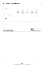
POSSIBLE SYSTEM CONFIGURATION 


Summary of Contents for BS 286

Page 1: ...ER SUPPLY USER MANUAL February 2011 ASL Intercom BV DESIGNED MANUFACTURED BY ASL Intercom B V Zonnebaan 42 3542 EG Utrecht The Netherlands Tel 31 0 30 2411901 Fax 31 0 30 2667373 Email info asl inter com Web www asl inter com ...

Page 2: ...NTY 4 4 0 MECHANICAL INSTALLATION 4 5 0 MAINS POWER SAFETY EARTH 4 6 0 GENERAL DESCRIPTION 4 7 0 FRONT PANEL CONTROLS CONNECTOR 5 8 0 REAR PANEL CONTROLS CONNECTORS 5 9 0 TECHNICAL SPECIFICATIONS 5 10 0 PARTY LINE TECHNICAL CONCEPT 6 11 0 CABLING 6 12 0 EARTHING CONCEPT 7 13 0 BS 286 BLOCK DIAGRAM 7 14 0 POSSIBLE SYSTEM CONFIGURATION 8 ...

Page 3: ...g the apparatus power cord by gripping the power plug not the cord 11 Insert the plug properly Do not defeat the safety purpose of the polarized or grounding type plug An American polarized AC line plug has two blades with one wider than the other This plug will fit only one way into the power outlet This is a safety feature If you are unable to insert the plug fully into the outlet try reversing ...

Page 4: ...Hz and at least 60 watts The outlet should have a clean earth Avoid using mains power outlets which also power dimmer controlled lighting equipment The wires in the mains lead are color coded green yellow Earth safety ground blue Neutral brown Live In case the wires in the mains lead do not correspond with the colored markings identifying the terminals in your mains plug proceed as follows The wir...

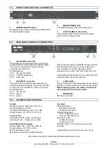
Page 5: ... level When mic level is selected 30V DC phantom power is supplied to pin 2 and 3 of the AUX input connector With the MIC GAIN trimmer one can adjust the input sensitivity when mic level is selected 6 FUSE Holder The fuse protects the BS 286 against severe internal damage in case of malfunction in the power section Before replacing a fuse the mains cord must be disconnected from the mains outlet 7...

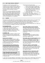
Page 6: ...cially when the cable is subjected to bending during operation or installation Cable screens to XLR pin 1 The screen of each separate microphone cable and or the screen of each single pair in a multi pair cable should be connected to pin 1 of each XLR 3 connector Do not connect these screens to the metal housing of ASL unitst or XLR 3 wall boxes See section Earthing Concept Connect metal cable tru...

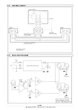
Page 7: ...PAGE 7 User Manual BS 286 February 2011 ASL Intercom BV 12 0 EARTHING CONCEPT 13 0 BS 286 BLOCK DIAGRAM ...

Page 8: ...PAGE 8 User Manual BS 286 February 2011 ASL Intercom BV 14 0 POSSIBLE SYSTEM CONFIGURATION ...

Reviews: