PAGE 5
User Manual PS 680 / Issue 2010 © ASL Intercom BV
6.0
MAINS POWER
WARNING: This appliance must be earthed
The PS 680 may be connected to a mains power
outlet of 100 - 240 Volts, 50
– 60 Hz, 150 watts.
The outlet should have a clean earth. Avoid using
mains outlets which also power dimmer controlled
lighting equipment.
Fuse type for all voltages: T 1250
The wires in the mains lead are color coded in
accordance with the following code:
Green-and-yellow:
Earth / safety ground
Blue:
Neutral
Brown:
Live
In case the colors of the wires in the mains lead do
not correspond with the colored markings
identifying the terminals in your plug, proceed as
follows:
The wire which is colored green-and-yellow
must be connected to the terminal in the
plug which is marked with the letter „E‟, or
by the earth symbol or colored green.
The wire which is colored blue must be
connected to the terminal which is marked
with the letter „N‟ or colored black.
The wire which is colored brown must be
connected to the terminal which is marked
with the letter „L‟ or colored red.
Safety Earth
The green-and-yellow wire of the mains cord must
always be connected to the electrical installation
safety earth or ground. It is essential for personal
safety as well as for proper operation of the PS 680
and the connected user stations. This wire is
internally connected to all exposed metal surfaces
of the PS 680. Any rack framework into which this
unit is mounted should be connected to the same
grounding circuit.
Powering Up Procedure
Make sure that the red power switch on the
left side of the front panel is OFF.
Connect the power cord to the rear of the
station.
Plug the other end of the power cord into a
properly grounded mains outlet.
Turn on the power with the red button.
The red overload LED lights up for about 3
seconds and then extinguishes. Now the
green power LED is lit, indicating the PS
680 is active
7.0
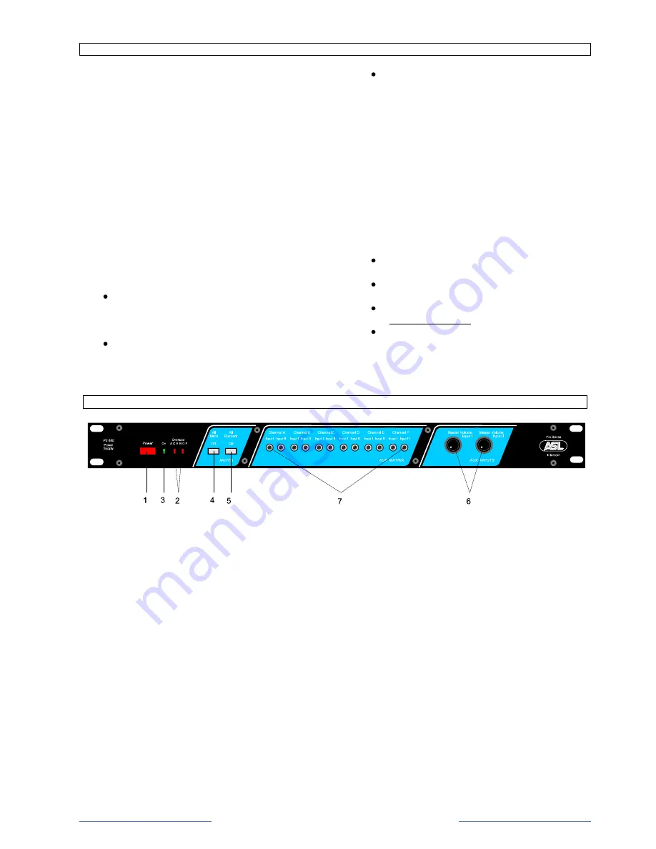
FRONT PANEL CONTROLS
1
POWER ON/OFF switch
Mains power push button for switching ON and OFF
the internal power supplies
2
OVERLOAD LEDs
There is an overload LED for channel A, C and E
(powered by PSU 1) and an overload LED for
channel B, D and F (powered by PSU 2).
An overload LED illuminates if a circuit breaker has
shut off the 30V DC line power due to overload.
A cause for overload can be too many user stations
connected or a short-circuit in the interconnecting
cables. The circuit breaker resets automatically 3
seconds after the cause of the overload has been
removed, restoring the line power. During short-
circuit the overload LED flashes every 3 seconds.
Every time mains power is switched on the LED is
lit for a few seconds.
3
POWER LED
This LED illuminates if line power is supplied by the
internal power supply
4
ALL MICS ON/OFF button
With this push button all microphones of the
connected stations can be muted
5
ALL BUZZERS ON/OFF button
With this push button all buzzers of the connected
stations can be muted
6
AUX MASTER VOLUME control knobs
These knobs adjust the level of each aux input
signal to the intercom lines
7
AUX MATRIX trimmers
These trimmers control the volume of each AUX
input signal as sent to each channel A - F


