


13
309879
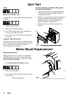
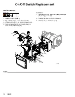
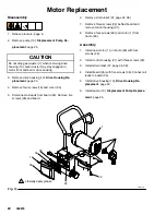
Motor Brush Replacement
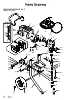
4. Fig. 5. Push in spring clip (A) to release hook (B)
from brush holder (C). Pull out spring clip (A).
5. Fig. 5. Pull brush lead (D) out of terminal (E).
Remove brush (F).
Fig. 5
A
B
E
D
F
C
1
1
Motor lead; do not disconnect
2
Minimum 0.5” (12.5 mm)
03881
3
Included in Brush Repair Kit
3
2
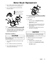
6. Inspect commutator for excessive pitting, burning
or gouging. A black color on commutator is normal.
Have commutator resurfaced by a motor repair
shop if brushes wear too fast.
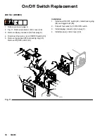
Motor Brush Installation
CAUTION
When installing brushes, follow all steps carefully to
avoid damaging parts.
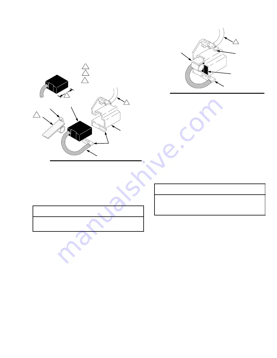
1. Fig. 6. Install new brush (F) with lead into brush
holder (C).
2. Fig. 5. Slide brush lead (D) into terminal (E).
3. Fig. 6. Install spring clip (A). Push down to set
hook (B) into brush holder (C).
Fig. 6
03881
1
B
C
E
F
4. Repeat for other side.
5. Test brushes.
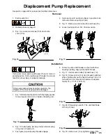
a. Remove pump (13);
Displacement Pump
Replacement
, page 25.
b. With sprayer OFF, turn pressure control knob
fully counterclockwise to minimum pressure.
Plug in sprayer.
c. Turn sprayer ON. Slowly increase pressure
until motor is at full speed.
CAUTION
Do not run sprayer dry for more than 30 seconds
while checking brushes to avoid damaging displace-
ment pump packings.
6. Install brush inspection covers and gaskets.
7. Break in brushes.
a. Operate sprayer 1 hour with no load.
b. Install pump (13);
Displacement Pump Re-
placement
, page 25.
Summary of Contents for 2300
Page 31: ...31 309879 Notes ...
Page 35: ...35 309879 Notes ...


