


25
309879
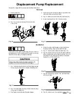
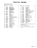
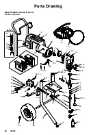
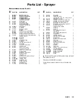
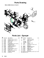
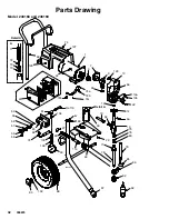
Displacement Pump Replacement
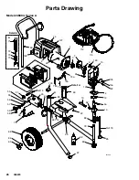
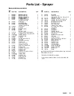
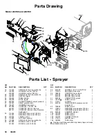
See parts on page 26 for sprayer part number references.
Removal
1. Flush pump (13).
2. Relieve pressure
;
page 6.
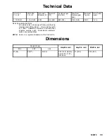
3. Fig. 16. Loosen two screws (10b) and rotate
cover (10a).
Fig. 16
9a
10b
10a
ti6016a
4. Cycle pump until pump pin (9a) is in position to be
removed. Remove pump pin (9a).
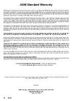
5. Fig. 17. Remove suction tube (78) and hose (19).
6. Loosen pump jam nut (12). Unscrew pump.
Fig. 17
78
12
19
ti6750a
Installation
If pin works loose, parts could break off due to force of
pumping action. Parts could project through the air and
result in serious injury or property damage.
CAUTION
If the pump locknut loosens during operation, the
threads of the drive housing will be damaged.
1. Fig. 18. Extend pump piston rod fully. Apply grease
to top of pump rod at (A) or inside connecting rod.
Fig. 18
A
ti6753a
2. Fig. 16. Install pump pin (9a). Verify retainer spring
is in groove of pump pin.
3. Push pump up until pump threads engage.
4. Screw in pump until threads are flush with drive
housing opening. Align pump outlet to back.
5. Fig. 17. Install suction tube (78) and hose (19).
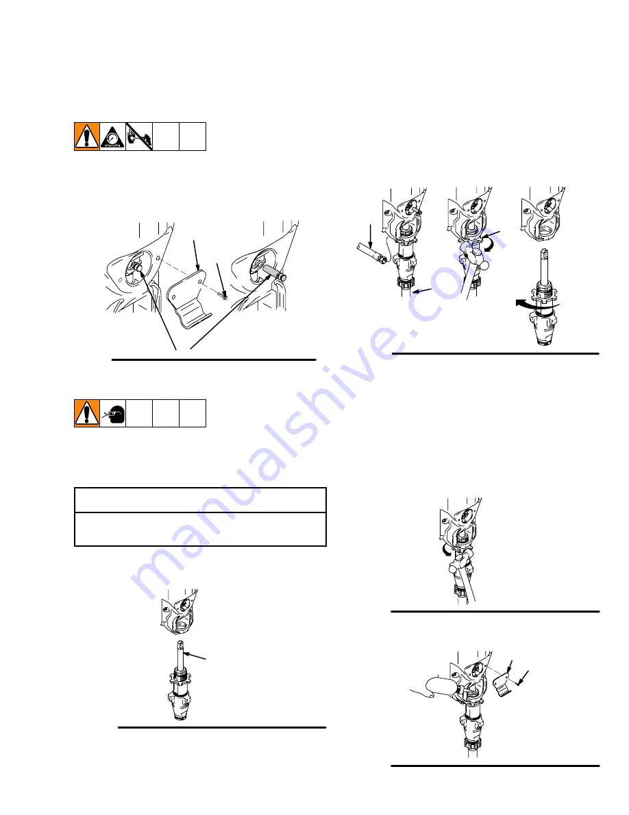
6. Fig. 19. Screw jam nut (12) up onto pump until nut
stops. Tighten jam nut by hand, then tap 1/8 to 1/4
turn with a 20 oz (maximum) hammer to approxi-
mately 75
5 ft--lb (102 N
¡
m).
Fig. 19
ti6751a
7. Fig. 20. Fill packing nut with TSL until fluid flows
onto top of seal.
Fig. 20
10b
10a
ti6752a
8. Fig. 16. rotate cover (10a); tighten screws (10b).
Summary of Contents for 2300
Page 31: ...31 309879 Notes ...
Page 35: ...35 309879 Notes ...


