

5
309879
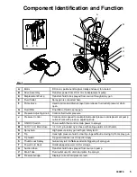
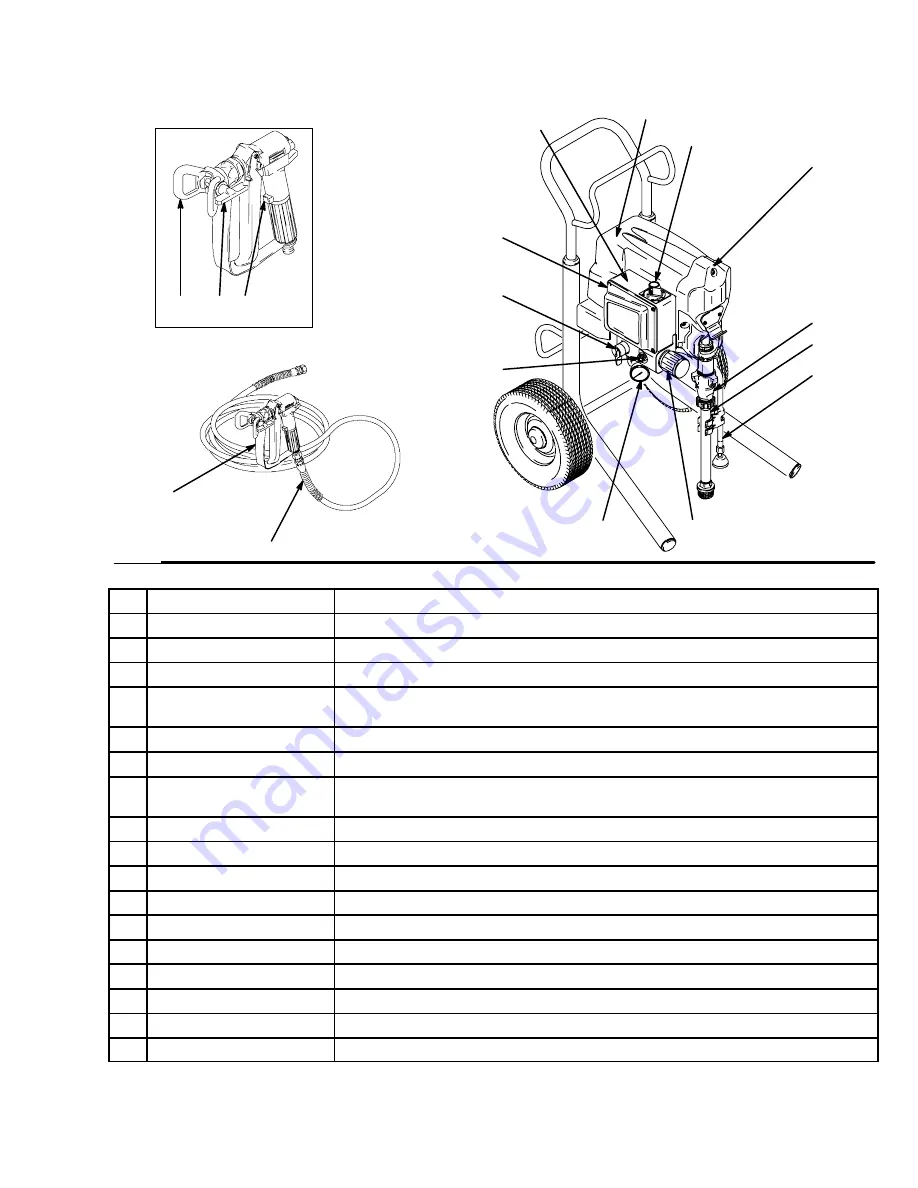
Component Identification and Function
Fig. 1
R
P S
N
M
D
B
H
F
E
A
U
V
J
G
K
W
ti6749a
A
Motor
DC motor, permanent magnet, totally enclosed, fan cooled
B
Drive Assembly
Transfers power from DC motor to displacement pump
D
Displacement Pump
Transfers fluid to be sprayed from source through spray gun
E
Fluid Outlet
Spray gun is connected here
F
Prime Valve
Used to prime and drain sprayer (also relieves fluid outlet pressure) when
open
G
Fluid Filter
Final filter of fluid to spray gun
H
Pressure Adjusting Knob
Controls fluid outlet pressure
J
Pressure Control
Controls motor speed to maintain fluid outlet pressure at displacement pump
outlet. Works with pressure adjusting knob.
K
ON/OFF Switch
Power switch that controls main power to sprayer
M
50 ft (15 m) Main Hose
1/4 in. ID, grounded, nylon hose with spring guards on both ends
N
Spray Gun
High pressure spray gun with gun safety latch
P
Tip
Uses high pressure fluid to clear tip clogs without removing tip from spray gun
R
Tip Guard
Tip guard reduces risk of injection injury
S
Thumb Lock Safety
Gun safety latch inhibits accidental triggering of spray gun
T
Power Cord Rack
Holds wrapped power cord for storage
U
Suction Hose
Transfers fluid to be sprayed from source to pump
V
Drain Tube
Fluid outlet used to drain and prime the sprayer
W
Pressure Gauge
Displays current fluid pressure level
Summary of Contents for 2300
Page 31: ...31 309879 Notes ...
Page 35: ...35 309879 Notes ...


