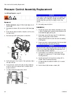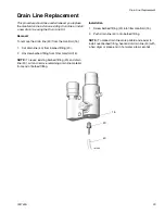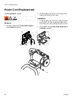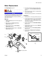
Control Board Replacement
24
332763A
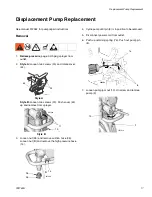
Installation
1.
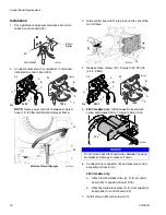
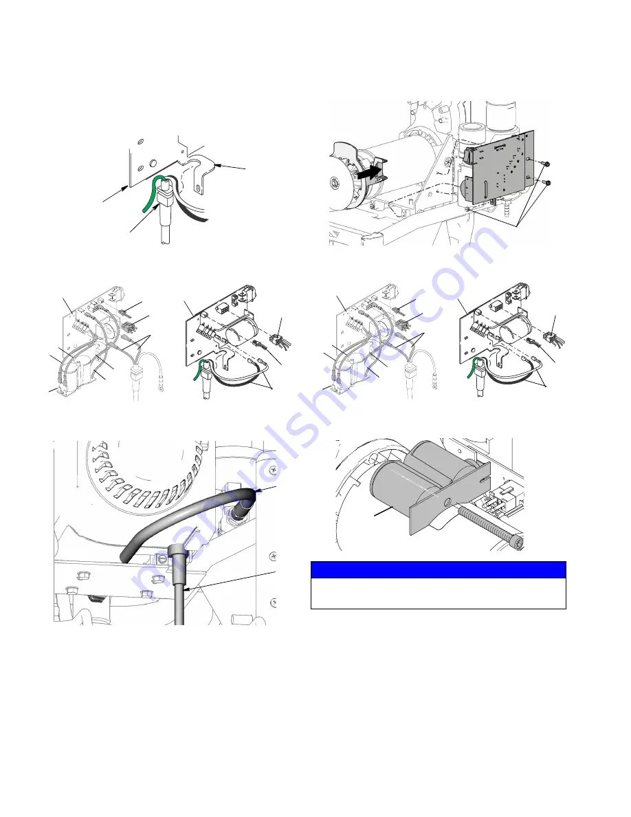
Push grommet and power cord wires into strain
relief in control board (33).
2.
Connect power cord (C) connectors to terminals
indicated on control board (33).
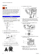
NOTE:
Route power cord (34) between coupled
hose (14) to filter manifold and sprayer frame.
3.
Slide control board (33) into place on the side of the
motor frame.
4.
Replace three screws (30). Torque to 30-35 in-lb
(3.4-3.9 N•m).
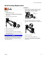
5.
230V models only:
Install capacitor board with
screw and bracket (33a). Torque to 35-40 in-lb.
6.
Connect motor connector (B) and pressure control
assembly connector (A).
230V models only:
a.
Attach red and black wires (H, F) from control
board (33) to capacitor board (33a).
b.
Attach red and black wires (D, E) from capacitor
board (33a) to control board (33).
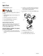
7.
Install shroud (29) with screws (30).
ti6122a
33
Grommet
Strain
Relief
ti6143a
230V
120V
33
C
A
B
B
A
H
D
E
F
C
33
33a
Bottom View of Sprayer
ti11555a
14
34
NOTICE
Do not pinch capacitor board wires between housing
and bracket. Damage to wires will occur.
ti11553a
30
ti6143a
230V
120V
33
C
A
B
B
A
H
D
E
F
C
33
33a
ti22266a
33a
Summary of Contents for 24U099
Page 33: ...Notes 332763A 33 Notes ...
Page 39: ...Notes 332763A 39 Notes ...


