background image

16

309423

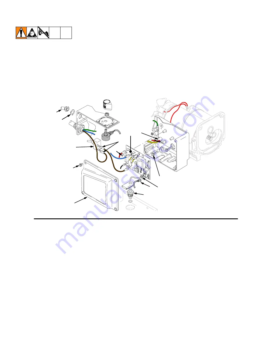
On/Off Switch Replacement

Removal

1.

Relieve pressure;

page 8.

2. Fig. 5. Remove four screws (18) and pressure

control cover (39).

3. Disconnect two wires (A) from ON/OFF

switch (23).

4. Remove toggle boot (25) and locking ring (24).

Remove ON/OFF switch (23).

Installation

1. Install new ON/OFF switch (23). Install locking ring

(24) and toggle boot (25).

2. Connect two wires (A) to ON/OFF switch.

3. Install pressure control cover (39) with four

screws (18).

Fig. 5

39

A

18

23

36

52

E

D

35

36

25

24

37

22

ti3917a

Summary of Contents for Zip-Spray 1900 Plus

Page 1: ...3000 psi 207 bar 20 7 MPa Maximum Working Pressure Important Safety Instructions Read all warnings and instructions in this manual Save these instructions 309971 309427 Hi Boy 233782 Series A B C D E F 309428 Model 233782 Series A B Model 246649 Series A B C D 311062 Model 233782 Series C D E F ti7508a ti8027a Stand 246649 Series A B C D Parts ...

Page 2: ...type material only For complete information about your fluid request the MSDS from the fluid distributor or retailer D Eliminate all ignition sources such as pilot lights cigarettes portable electric lamps and plastic drop clothes potential static arc D Keep work area free of debris including solvent rags and gasoline D Do not plug or unplug power cords or turn lights on or off when flammable fume...

Page 3: ...ributor for information D Route hoses and cables away from traffic areas sharp edges moving parts and hot surfaces D Do not kink or over bend hoses or use hoses to pull equipment D Keep children and animals away from work area D Comply with all applicable safety regulations PRESSURIZED ALUMINUM PARTS HAZARD Do not use 1 1 1 trichloroethane methylene chloride other halogenated hydrocarbon solvents ...

Page 4: ...4 309423 Component Identification and Function K E H B A D J G F V U T Fig 1 K E H B A D J G F V U T ti6013b R P S N M ti5875b ...

Page 5: ...or speed to maintain fluid outlet pressure at displacement pump outlet Works with pressure adjusting knob K ON OFF Switch Power switch that controls main power to sprayer M 50 ft 15 m Main Hose 1 4 in ID grounded nylon hose with spring guards on both ends N Spray Gun High pressure spray gun with gun safety latch P Spray Tip Uses high pressure fluid to clear tip clogs without removing tip from spra...

Page 6: ...uce sprayer performance Grounding and Electric Requirements D Ground sprayer gun through connection to a properly grounded fluid hose and pump D Ground fluid supply container Follow local code D Ground solvent pails used when flush ing Follow local code Use only conduc tive metal pails placed on a grounded surface such as concrete Do not place the pail on a non conductive surface such as paper or ...

Page 7: ...relieving pressure by hold ing metal part of spray gun firmly to side of a grounded metal pail then trigger gun Grounding and Electric Requirements Thermal Overload D Motor has a thermal overload switch to shut itself down if overheated D To reduce risk of injury from motor starting unexpectedly when it cools always turn power switch OFF if motor shuts down ti5851a ti6762a ...

Page 8: ... Spray Prime Drain valve in PRIME DRAIN position until you are ready to spray again D If you suspect the spray tip is clogged or that pressure has not been fully relieved after following the above steps VERY SLOWLY loosen tip guard retaining nut or hose end coupling to relieve pressure gradually Then loosen completely Clear hose or tip obstruc tion Follow Pressure Relief Procedure when you stop sp...

Page 9: ...To reduce risk of serious injury including electric shock D Do not touch moving or electric parts with fingers or tools while testing repair D Unplug sprayer when power is not required for testing D Install all covers gaskets screws and washers before you operate sprayer CAUTION D Do not run sprayer dry for more than 30 seconds Doing so could damage pump packings D Protect the internal drive parts...

Page 10: ...r to separate gun or tip instruction manual Basic Mechanical Problems 1 Pump 13 frozen or hardened paint 1 Thaw sprayer if water or water based paint has frozen in sprayer Place sprayer in warm area to thaw Do not start sprayer until thawed completely If paint hardened dried in sprayer replace pump packings See page 26 Displacement Pump Replace ment 2 Displacement pump connecting rod pin 9a Pin mu...

Page 11: ...s Be sure terminals are firmly connected Clean circuit board terminals Securely re connect leads 7 Motor thermal switch Yellow motor leads must have continuity through thermal switch 7 Replace motor See page 25 Motor Re placement 8 Brush cap missing or loose brush lead connec tions 8 Install brush cap or replace brushes if leads are damaged Seepage 14 Motor BrushRe placement 9 Brush length which m...

Page 12: ...ect grounded exten sion cord 8 Leads from motor to pressure control circuit board 35 for damaged or loose wires or con nectors Inspect wiring insulation and terminals for signs of overheating 8 Be sure male terminal blades are centered and firmly connected to female terminals Replace any loose terminal or damaged wiring Securely reconnect terminals 9 For loose motor brush leads and terminals See p...

Page 13: ...ure Visually inspect capacitor near terminals Ensure that orange safety re lief plug is intact 7 Replace capacitor Motor runs but pump does not stroke 1 Displacement pump pin 9a damaged or missing page 26 1 Replace pump pin if missing Be sure re tainer spring 9b is fully in groove all around connecting rod page 26 2 Connecting rod assembly 9 for damage page 24 2 Replace connecting rod assembly pag...

Page 14: ...at about two revolutions per second 2 If uneven or no resistance check for broken brush springs brush leads motor leads loose brush terminal screws motor lead terminals worn brushes Repair as needed page 14 3 If still uneven or no resistance replace motor page 25 9578A Fig 2 F G 39 Motor Brush Replacement Motor Brush Removal Replace brushes worn to less than 1 4 in 6 mm Check both sides See Parts ...

Page 15: ... To Motor D 8 If replacement brush harness has 2 yellow wires C cut strip and crimp the 2 yellow wires D from the motor and butt splice E on the replace ment harness 9 Inspect commutator for excessive pitting burning or gouging A black color on commutator is normal Have commutator resurfaced by a motor repair shop if brushes wear too fast 10 Test brushes a Remove pump 13 Displacement Pump Replacem...

Page 16: ...ect two wires A from ON OFF switch 23 4 Remove toggle boot 25 and locking ring 24 Remove ON OFF switch 23 Installation 1 Install new ON OFF switch 23 Install locking ring 24 and toggle boot 25 2 Connect two wires A to ON OFF switch 3 Install pressure control cover 39 with four screws 18 Fig 5 39 A 18 23 36 52 E D 35 36 25 24 37 22 ti3917a ...

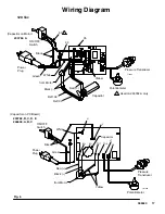
Page 17: ...llow White Black Black Capacitor TI0060 Green 60 35 34 Ref134 Ref133 Capacitor on Motor 1 1 Used on 233782 A only 233782 A 233782 B C D E 246649 A B C Pressure Transducer ON OFF Switch Power Plug Potentiometer from Motor Capacitor Black Green White Yellow Black Red N L M M TO1 TO2 J7 J8 ti2159a Capacitor on PC Board ...

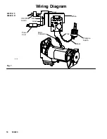
Page 18: ...18 309423 Wiring Diagram Fig 7 ti7415a Motor Connector ON OFF Switch Black White White Pressure Switch Black Black Green Power Cord 233782 F 246649 D ...

Page 19: ...ly Sprayer shuts down and LED continues to blink two times repeatedly Run away pressure Pres sure greater than 4500 psi 310 bar 31 MPa Replace motor control board See following Motor Control Board procedure Three times repeatedly Sprayer shuts down and LED continues to blink three times repeatedly Pressure transducer is faulty or missing Check transducer connection Open drain valve Substitute new ...

Page 20: ...from transducer 4 Remove five screws 36 and circuit board 35 Installation 1 Clean pad on rear of motor control board Apply small amount of thermal compound 073019 to pad 2 Fig 5 Install motor control board 35 with five screws 36 3 Connect to motor control board 35 D Lead E to transducer D Lead D to potentiometer D Two line voltage leads D Four motor leads two yellow black and red 4 Install cover 3...

Page 21: ...transducer lead plastic connector up through transducer grommet 28 3 Install filter housing 45 with two screws 22 4 Connect lead E to motor control board 35 5 Install cover 39 with four screws 18 Pressure Adjust Potentiometer Removal Refer to Fig 5 and 6 1 Relieve pressure page 9 2 Remove four screws 18 and cover 39 3 Disconnect all leads from motor control board 35 4 Remove five screws 36 and boa...

Page 22: ...onnector pressure control connector white wire to control board 8 and black wire to switch 4 4 Remove 4 screws 9 and control board 8 Installation 1 Assemble control board 8 with 4 screws 9 2 Connect motor connector pressure control con nector white wire to control board 8 and black wire to switch 4 3 Install cover 16 with 4 screws 17 Fig 8 15 14 13 12 11 10 6 5 4 1 3 9 2 18 17 8 16 2 19 7 ti7414a ...

Page 23: ...See Fig 8 Page 22 NOTE The pressure control has been preset at the fac tory to the design stall pressure 1 Apply red thread locking adhesive provided in kit to the brass threads of the pressure control 12 2 Assemble pressure control 12 into fitting 11 and torque to 140 in lbs 12 ft lbs Do not pinch or damage the wires on the pressure control 3 Assemble the fluid manifold to the control box with 2 ...

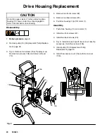
Page 24: ...Tip sprayer up Remove two screws 18b and remove shroud 74 4 Remove two front screws 22 5 Remove two back screws 22 6 Pull drive housing 10 off of motor 1 Assembly 1 Push drive housing 10 onto motor 1 2 Install two front screws 22 3 Install two back screws 22 4 Fig 9 Install shroud 74 with two screw 18a Tip sprayer up Install two screws 18b 5 Install pump 13 Displacement Pump Replacement page 26 6 ...

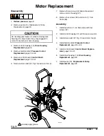
Page 25: ...1 6 Remove strain relief 37 Fig 13 and motor fan 2 7 Remove three screws 22 behind board and remove control housing 21 8 Remove four screws 22 and motor 1 from frame 63 Assembly 1 Install new motor 1 on frame 63 with four screws 22 2 Install control housing 21 with three screws 22 3 Install strain relief 37 Fig 13 and motor fan 2 4 Install fluid manifold Pressure Control Replacement page 20 or 22 ...

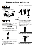
Page 26: ...operation the threads of the drive housing will be damaged 1 Fig 13 Extend pump piston rod fully Apply grease to top of pump rod at A or inside connecting rod Fig 13 A ti6753a 2 Fig 11 Install pump pin 9a Verify retainer spring is in groove of pump pin 3 Push pump up until pump threads engage 4 Screw in pump until threads are flush with drive housing opening Align pump outlet to back 5 Fig 12 Inst...

Page 27: ...27 309423 Notes ...

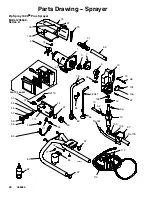
Page 28: ...rayer Model 246649 Series A 7 10 128 71 9 12 9b 1 74 9a 10a 59 62 84 Ref 103 113 85 13 10b 3 87 92 31 77 63 Ref 19 31 19 49 82 78 65 68 45 58 57 56 55 53 84 38 Ref 84 Ref 78 47 69 22 22 112 67 70 86 2 75 18 18 62 127 126 22 67 PARTS PAGE 40 114 135 ti3920c ...

Page 29: ...55 57 224807 ASSY cam drain valve 1 58 111600 PIN grooved 1 59 187625 HANDLE valve drain 1 62 162453 NIPPLE 1 4 npt m x 1 4 npsm 2 63 241858 FRAME stand mount 1 65 195177 HOLDER suction tube 1 67 107310 PLUG tubing 4 68 115506 SCREW slot hd hex washer hd 1 69 195425 HANDLE sprayer 1 70 100016 WASHER lock 1 71 108063 GRIP handle 1 74 245439 SHROUD motor 1 includes 18 75 126 127 75 198933 VENT side ...

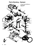
Page 30: ...74 9a 10a 59 62 84 Ref 103 113 85 13 10b 3 87 92 77 63 19 78 65 68 58 57 56 55 53 Ref 84 Ref 78 69 22 22 112 67 70 2 75 18 18 127 126 22 67 PARTS PAGE 40 135 82 45 84 47 86 61 Ref 19 ti6017b 114 Zip Spray 1900 Plust Sprayer Model 246649 Series B C 49 81 80 ...

Page 31: ...625 HANDLE valve drain 1 61 15E539 NIPPLE 1 4 npsm x 1 8 npsm Series B only 1 62 162453 NIPPLE 1 4 npt m x 1 4 npsm 1 63 241858 FRAME stand mount 1 65 195177 HOLDER suction tube 1 67 107310 PLUG tubing 4 68 115506 SCREW slot hd hex washer hd 1 69 195425 HANDLE sprayer 1 70 100016 WASHER lock 1 71 108063 GRIP handle 1 74 245439 SHROUD motor 1 includes 18 75 126 127 75 198933 VENT side 1 77 115723 S...

Page 32: ...Sprayer Model 246649 Series D 7 10 128 71 9 12 9b 1 74 9a 10a 59 62 84 Ref 103 112 85 13 10b 3 87 92 77 63 Ref 19 19 82 78 65 68 58 57 56 55 53 84 Ref 84 Ref 78 69 22 113 67 70 86 75 18 127 126 22 67 135 61 45 114 22 77 PARTS PAGE 41 ti7411b 49 81 47 80 2 ...

Page 33: ...39 NIPPLE 1 4 npsm x 1 8 npsm 1 62 162453 NIPPLE 1 4 npt m x 1 4 npsm 1 63 241858 FRAME stand mount 1 65 195177 HOLDER suction tube 1 67 107310 PLUG tubing 4 68 115506 SCREW slot hd hex washer hd 1 69 195425 HANDLE sprayer 1 70 100016 WASHER lock 1 71 108063 GRIP handle 1 74 253275 SHROUD motor 1 includes 18 126 127 75 15G971 VENT side 1 77 115723 SCREW mach pnhd self drill 3 78 244354 HOSE suctio...

Page 34: ...through 134 not used on later models See Parts List Sprayer page 33 7 71 9 12 9b 1 74 9a 10a 59 62 112 13 10b 3 85 31 77 63 31 19 49 72 45 58 57 56 55 53 84 38 84 78 47 22 22 113 67 10 86 2 75 18 18 62 127 126 22 67 130 131 134 133 PARTS PAGE 40 114 69 87 65 82 81 80 66 70 1 88 132 ti3921b ...

Page 35: ...cam drain valve 1 58 111600 PIN grooved 1 59 187625 HANDLE valve drain 1 62 162453 NIPPLE 1 4 npt m x 1 4 npsm 2 63 241934 FRAME cart 1 65 195497 HOOK pail 1 66 101242 RING retaining external 2 67 107310 PLUG tubing 4 69 241938 HANDLE cart 1 70 106062 WHEEL semi pneumatic 2 71 115480 KNOB t handle 2 72 105521 PLUG tubing 4 74 245439 SHROUD motor kit 1 includes 18 75 126 127 75 198933 VENT side 1 7...

Page 36: ...rayer Model 233782 Series C D E Series C shown 7 71 9 12 9b 1 74 9a 59 62 112 3 63 19 72 58 57 56 55 53 22 113 67 10 2 75 18 18 127 126 22 67 PARTS PAGE 40 69 87 1 88 13 22 10b 49 81 10a 84 61 45 47 114 80 77 70 128 ti7031b 85 84 78 82 86 89 76 91 90 ...

Page 37: ... 111600 PIN grooved 1 59 187625 HANDLE valve drain 1 61 15E539 NIPPLE 1 4 npsm x 1 8 npsm 2 62 162453 NIPPLE 1 4 npt m x 1 4 npsm 2 63 241934 FRAME cart 1 67 107310 PLUG tubing 4 69 241938 HANDLE cart 1 70 119451 WHEEL semi pneumatic 2 71 115480 KNOB t handle 2 72 105521 PLUG tubing 4 74 245439 SHROUD motor kit 1 includes 18 75 126 127 75 198933 VENT side 1 76 15B652 WASHER suction series D 1 77 1...

Page 38: ... 1900 Sprayer Model 233782 Series F 63 19 9a 12 13 22 10b 67 49 66 81 10a 68 10 87 7 9 3 1 69 71 57 55 56 59 58 77 70 84 61 53 72 45 47 114 126 18 22 80 74 127 75 112 113 17 9b PARTS PAGE 41 14 ti7413b 85 84 78 82 86 89 76 91 90 2 105 ...

Page 39: ...1600 PIN grooved 1 59 187625 HANDLE valve drain 1 61 15E539 NIPPLE 1 4 npsm x 1 8 npsm 1 63 241934 FRAME cart 1 66 15B197 CAP leg 2 67 107310 PLUG tubing 2 68 115097 SCREW curved head 2 69 241938 HANDLE cart 1 70 119451 WHEEL semi pneumatic 2 71 115480 KNOB t handle 2 72 105521 PLUG tubing 2 74 253275 SHROUD motor kit 1 includes 18 75 126 127 75 15G971 VENT side 1 76 15B652 WASHER suction 1 77 119...

Page 40: ...5 195428 BOOT toggle 1 26 236352 POTENTIOMETER adjust pressure 1 27 116167 KNOB potentiometer 1 28 195423 GROMMET transducer 1 29 241729 CORD SET power 1 30 114421 BUSHING strain relief 1 32 196904 LABEL control 1 33 112382 NUT shaft sealing 1 34 115498 SCREW slot hd hex washer hd 1 see page 17 35 BOARD control see page 17 241989 233782 A 1 245892 233782 B C D E 1 245892 246649 A B C 1 36 115494 S...

Page 41: ...ITCH toggle 1 5 195428 BOOT toggle 1 6 15G388 CORD power 1 7 115498 SCREW mch slot hex wash hd 1 8 253118 CONTROL board 190ES LC 1 9 115494 SCREW mach phillips pan hd 4 10 103338 PACKING o ring 1 11 15G424 ADAPTER extension switch pressure1 12 253117 CONTROL pressure 190 120V includes 15 1 13 107146 RING retaining ext 1 14 15G484 KNOB control plastic 1 14a 15H147 BAFFLE knob pressure 1 15 15G475 L...

Page 42: ...3 680 180 0 38 1 25 0 019 1 4 in Basic Sprayer Wetted Parts zinc plated carbon steel polyurethane polyethylene stainless steel PTFE acetal chrome plating leath er V Maxt UHMWPE aluminum stainless steel tungsten carbide Dimensions Weight lb kg with Hose and Gun Height in cm Length in cm Width in cm Cart 59 26 8 40 101 6 21 5 54 6 21 53 3 Stand 47 21 3 18 45 7 17 43 2 14 5 36 8 ...

Page 43: ...43 309423 Notes ...

Page 44: ...DING BUT NOT LIMITED TO WARRANTY OF MERCHANTABILITY OR WARRANTY OF FITNESS FOR A PARTICULAR PURPOSE ASM s sole obligation and buyer s sole remedy for any breach of warranty shall be as set forth above The buyer agrees that no other remedy including but not limited to incidental or consequential damages for lost profits lost sales injury to person or property or any other incidental or consequentia...

Reviews: