20
21
English
ELMON
classic
41-312 / ELMON
classic
41-812
Safety Relais
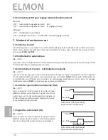
9.4 Connection of control circuits
The control circuits to be monitored are to be connected to the
STOP 1
and
STOP 2
.terminals If a redundant
continuation of the switching contacts is not desired, a bridge can be inserted between
STOP1
and
STOP2
.
In the event of any redundant use of the switching contacts only voltages with the same potential
may be connected. The use of different voltage potentials does not correspond to any intended
use within specifications.
Depending on the nominal current, the control circuits are to be protected by a corresponding fuse or the
nominal current on the control circuits must be limited to the maximum value by means of other measures.
9
.5 Connection Reset
For the operating mode “manual reset” the necessary reset switch must be connected to the
RESET
terminals.
9.6 Connection of signaling contact
The signaling
AUX
contact only serves as an auxiliary contact (signaling, display etc.) and must not be inte
-
grated into the safety circuit.
Safety contact edge SENTIR
edge
:
A maximum of 5 SENTIR edge devices can be connected in series. The maximum total length of the SENTIR
edge must not exceed 100 m.
The length of a SENTIR edge can be up to 25 m.
The total line length of the series-connected SENTIR edge must not exceed 25 m.
Safety contact bumper SENTIR
bumper
:
A maximum of 5 SENTIR bumper devices can be connected in series. The maximum total length of the SENTIR
bumpers must not exceed 15 m.
The length of a SENTIR bumper may be up to 3 m.
The total line length of the series-connected SENTIR bumpers must not exceed 25 m.
Safety contact mat SENTIR
mat
:
A maximum of 10 SENTIR mats can be connected in series. The maximum total surface area must not exceed
10 m2.
The size of a SENTIR mat can be up to 1350 x 2350 mm.
The total line length of the series-connected SENTIR mat must not exceed 25 m.
Before connecting the series-connected
sensors, it is recommended to measure the resistance value of the
wiring. In the case of non-operated
sensor
s the resistance must be 8.2 kΩ ± 500 Ω. If the
sensor is operated,
the resistance must not exceed 500 Ω.
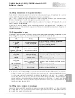
Fig. 1: Interconnecting several sensors, here using the example of the safety contact edge
Sensor 1
Sensor 2
Sensor „n“
O
C
2
2
2
2


