16
17
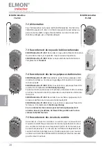
7. Connecti ng the device
7.1 Prerequisites
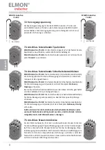
• The signal cable must not be placed parallel to the motor cable or other power cables.
• The supply voltage used for the ELMON inducti ve 71-242 and the ELMON inducti ve 71-942 must comply
with the requirements for safety low voltage (SELV).
• Cables installed outdoors or outside of the switching cabinet must be protected appropriately.
•
The protecti on class specifi ed for this device is only ensured if the supply lines have been properly clamped
to the screw connecti ons.
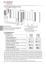
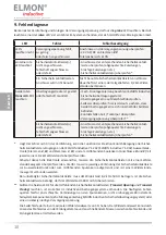
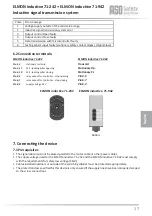
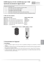
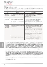
Pulse
Error message
1
Voltage supply outside of the valid value range
2
Inducti ve signal transmission system error
3
Output control Open faulty
4
Output control Close faulty
5
Data transmission with microcontroller faulty
6
Testi ng sensor input faulty (stati onary safety contact edges) (Open/Close)
Bott om
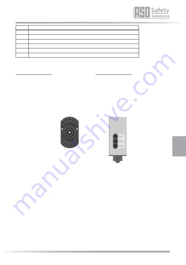
ELMON inducti ve 71-942
Transmit
Stati onary Op.
Stati onary Cl.
Pin 4, 5
Pin 6, 7
Pin 8, 9
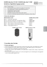
ELMON inducti ve 71-242
Pin 1, 2
stati onary coil core
Pin 3, 11
SCE - leading pillar opening
Pin 3, 10
SCE - leading pillar closing
Pin 4, 5
relay output for controller - stop opening
Pin 6, 7
relay output for controller - stop closing
Pin 8, 9
supply voltage 24 V
6.2 Connecti on termi
nals
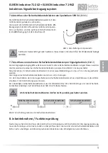
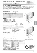
ELMON inducti ve 71-242 + ELMON inducti ve 71-942
Inducti ve signal transmission system
ELMON inducti ve 71-242
ELMON inducti ve 71-942
1
2
3
4
5
6
7
8
9
10
11
English

