18
19
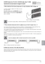
ASO safety contact edges must not be connected in parallel.
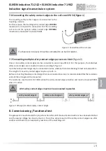
7.6 Connecti ng the safety contact edges to the coil core SPK 54 (fi gure 1)
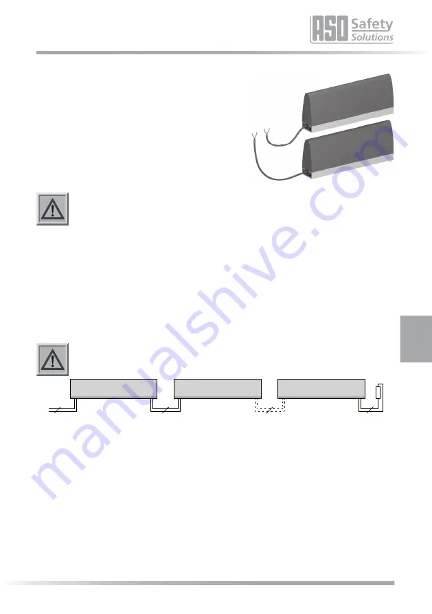
7.7 Connecti ng multi ple safety contact edges per sensor circuit
(fi gure 2)
One or more safety contact edges can be connected to sensor input
O
or
C
. For this purpose, the individual
safety contact edges are connected in series according to fi gure 2.
Up to fi ve safety contact edges may be connected in series, whereby the total cable length must not exceed 25 m.
The length of one safety contact edges may be up to 25 m.
Before connecti ng the safety contact edges that are connected in series, it is recommended that the resistance
value of the arrangement be measured.
The resistance must be 8.2 kΩ ± 500 Ω when the safety contact edge is inacti ve and must not exceed 500 Ω
when it is acti ve.
If a channel is not used, it must be connected to an 8,2 kΩ resistor.
The travelling safety contact edges are connected to the
travelling coil core.
For this purpose, the travelling safety contact edge
CLOSING
movement is connected to connecti on
C
of the travelling
coil core and the opti onal safety contact edge
OPENING
movement is connected to connecti on
O
.
8. Commissioning / functi onal test
The gate system must be tested for proper functi on aft er all of the electrical connecti ons have been established
and the supply voltage has been turned on. To do this, acti vate each of the safety contact edges one aft er
another and check the corresponding reacti ons of the switching unit.
Figure 2: Wiring of multi ple safety contact edges
English
ELMON inducti ve 71-242 + ELMON inducti ve 71-942
Inducti ve signal transmission system
safety c
ontact edg
e
CLOSING
movemen
t
safety c
ontact edg
e
OPENING
movemen
t
O
C
Figure 1: Connecti on at the coil core
safety contact edges 1
safety contact edges 2
safety contact edges „n“
O
C
2
2
2
2

