16
Inductive signal transmission system
4
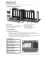
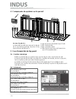
System components fitted to the gate
5
Device overview
5.1
Mechanical mounting
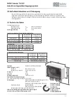
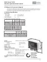
Polycarbonate housing with screw connections for on-wall mounting in harsh environments
The switching unit is to be professionally mounted at a suitable location After removing the cover,
the housing can be mounted with four screws
The switching unit may be mounted in any orientation To prevent moisture penetration, it should,
however, be installed so that the cable conduits point downward
5.2
Signal Indicators
ISK 71-24
Transmit Opening
Stationary Opening
Transmit
Stationary
Power
ISK 71-242
3
3 11
10 1 2
2
2
2
2
4
3
Gate opens
Gate closes
sa
fe
ty c
on
tact edg
es
OPEN
mo
vemen
t
sa
fe
ty c
on
tact edg
es
OPEN
mo
vemen
t
sa
fe
ty c
on
tact edg
es
OPEN
mo
vemen
t
sa
fe
ty c
on
tact edg
es
CL
OSE
mo
vemen
t
sa
fe
ty c
on
tact edg
es
CL
OSE
mo
vemen
t
sa
fe
ty c
on
tact edg
es
CL
OSE
mo
vemen
t
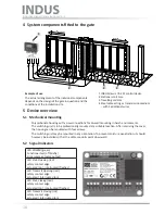
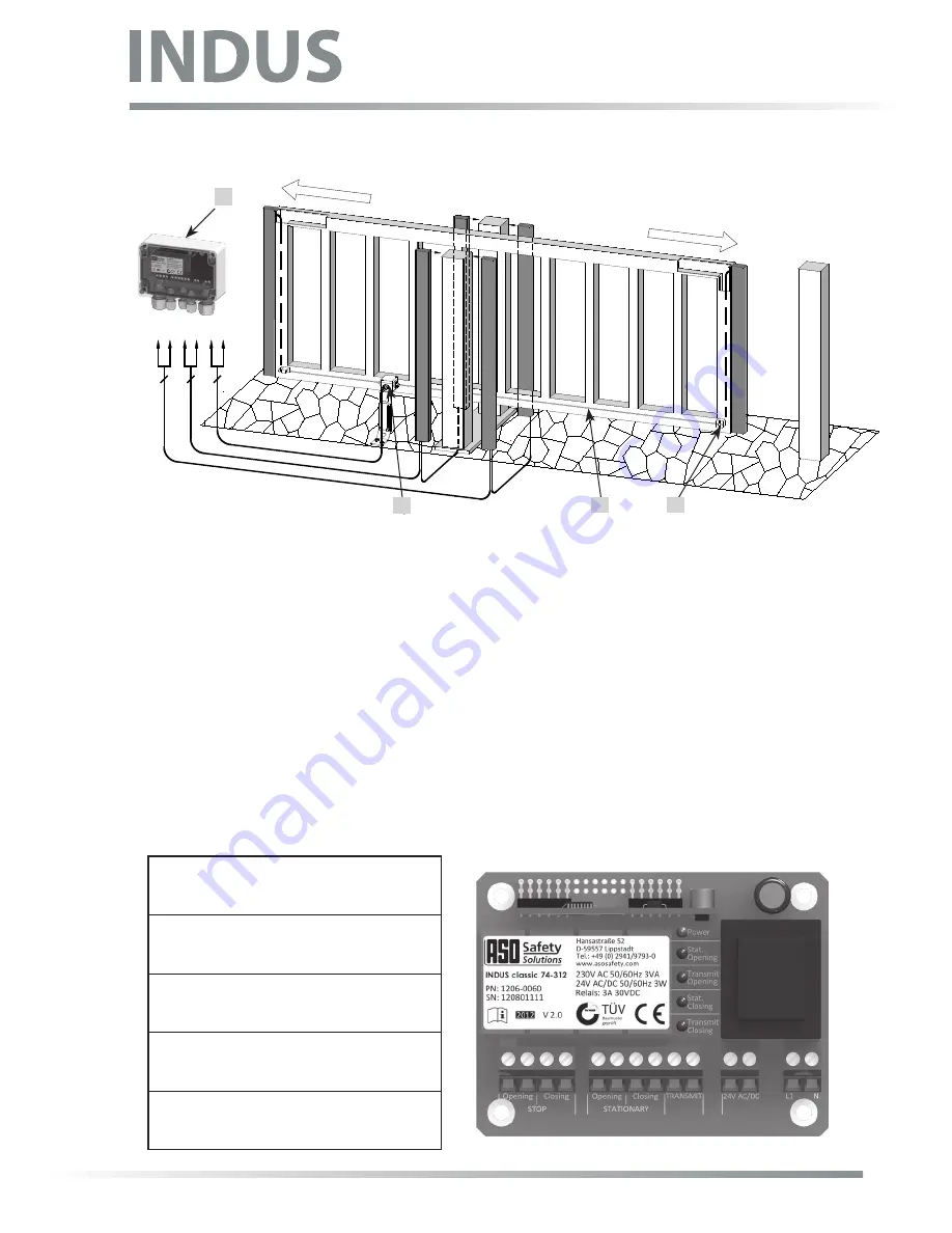
1 INDUS classic 74-312 control device
2 Stationary coil core
3 Travelling coil core
4 Steel cable acting as transmission medium
- with 2 additional wires
Example of use
The actual arrangement of the individual components
depends on the design of the gate in question and the
conditions at the installation site
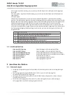
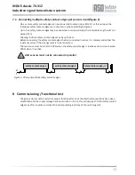
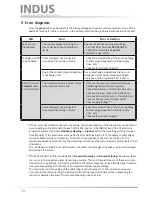
LED
POWER
(green)
Functional test (off briefly)
Error message (pulse output)
LED
Stat. Opening
(red)
safety contact edge
actuated (on) - interrupted (flashes)
LED
Transmit Opening
(red)
safety contact edge
actuated / interrupted (on)
LED
Stat. Closing
(red)
safety contact edge
actuated (on) - interrupted (flashes)
LED
Transmit Closing
(rot)
safety contact edge
actuated / interrupted (on)
opening closing
stationary
1
Summary of Contents for INDUS classic 74-312
Page 33: ...33 Notizen Notes Notes ...
Page 34: ...34 Notizen Notes Notes ...
Page 35: ...35 Notizen Notes Notes ...

