background image

16

SK 32-31 + SK 32-33 Safet�� Rela��

32-31 + SK 32-33 Safet�� Rela��

 Safet�� Rela��

Relay

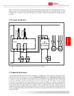
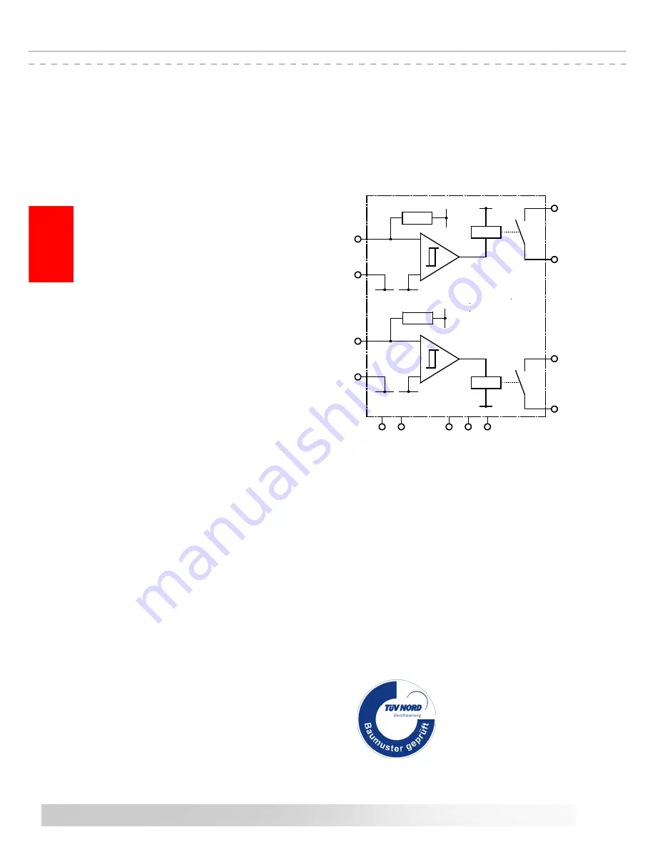
SK 32 block diagram

9. Technical specifications

Suppl�� voltage

Mains voltage 

U

Netz

  230 V AC 50/60Hz

Low voltage 

U

E


  24 V AC/DC ±10%

Power consumption 

P

max

      3 VA

Terminating resistor - sensor

nominal value 

R

A


  8,2 k�

upper switching point  R

AO 

> 16 k�

lower switching point   R

AU 

<   5 k�

Rela�� stages


nominal current DC 

    3 A    30 V DC

nominal current AC 

    3 A  250 V AC

Mechanical life-time 

    >10

6

  actuations

Safet�� rela�� switching times

Response time 


              < 5 ms

Turn-off time  


approx. 200 ms

Housing

Polycarbonate with transparent cover

Dimensions (HxWxD)

Housing 


120 x 122 x 56 mm

incl. M16 screw-fittings  140 x 122 x 56 mm
for snap-on rail mounting  

122 x 116 x 37 mm

Protection class

with screw-fittings  


IP65

with blanking plug  


IP54

Weight


650 g

Temperature range


-20 °C to +55 °C

Connection cable cross-section


single- or fine-stranded cable 0,5-2,5 mm

2

Safet�� categor��

EN ISO 13849-1:2008 Category 3 PL d

MTTFd 180 years, DC 90%

(Electronic)

MTTFd 3757 ��ears

(Electromechanics)

B10d 1000000

MTTFd 190 years (Nop 52560)

8. Taking out of service and disposal

The products manufactured by ASO are intended solely for commercial use (B2B). At the end of use, the 

products are to be disposed of according to all local, regional and national regulations. Products can also be 

returned to ASO, which will then dispose of them properly.

Certificate no.

44 205 10 384655-001
Test report no.

10 205 384655-001

English

+Ub

+Ub

Rre�

Rre�

N

L

1

24V A

C

/D

C

Rel

Rel

Ure�

Ure�

Stati

o

nar��

Opening

Stati

o

nar��

C

l

o

sing

St

o

p

Opening

St

o

p

C

l

o

sing

PE

Summary of Contents for SK 32-31

Page 1: ...Power Stationary Opening Transit Opening Stationary Closing STOP Opening STOP Closing STATIONARY Opening Closing 1 2 3 TRANSMIT 24V AC DC PE L1 N Manuel d utilisation SK 32 31 SK 32 33 Relais de sécurité Operating Manual SK 32 31 SK 32 33 Safety Relay Manuale di istruzione SK 32 31 SK 32 33 Relè di sicurezza Page 11 18 Page 19 26 Pagina 27 34 Gebruiksaanwijzing SK 32 31 SK 32 33 Veiligheidsrelais ...

Page 2: ...pplémentaires Componenti ausiliari Bijkomende componenten Funktionsprüfung Functional test Contrôle de fonction Controllo funzionale Functiecontrole Sicherheitssensoren reagieren auf Betätigung Safety sensor response to actuation Le senseur de sécurité réagit à l actionnement Il sensore di sicurezza reagisce all azionamento Veiligheidssensor reageert op activering Sicherheitssensoren reagieren auf...

Page 3: ...eitsbestimmungen und Schutzmaßnahmen 4 3 Allgemein 5 4 Bestimmungsgemäße Verwendung 5 5 Geräteübersicht 5 5 1 Signalanzeigen 5 5 2 Anschlussklemmen 5 5 3 Ausführungen und Montage 6 5 4 Anschluss von mehreren Signalgebern pro Signalgeberkreis 6 6 Inbetriebnahme 6 6 1 Voraussetzungen 6 6 2 Elektrischer Anschluss 6 6 3 Anwendungsbeispiel 7 7 Fehlersuche 7 8 Außerbetriebnahme und Entsorgung 8 9 Techni...

Page 4: ...ut sind Die Hinweise in dieser Anleitung sind unbedingt zu beachten und einzuhalten Elektrische Arbeiten dürfen nur von Elektrofachkräften durchgeführt werden Sicherheitsvorschriften der Elektrotechnik und der Berufsgenossenschaft sind zu beachten Bei Arbeiten am Schaltgerät ist dieses spannungsfrei zu schalten auf Spannungsfreiheit zu prüfen und gegen Wiedereinschalten zu sichern Werden die poten...

Page 5: ...rwendung Die bestimmungsgemäße Verwendung des Schaltgerätes ist der Einsatz als Schutzeinrichtung in Verbindung mit Sicherheitskontaktmatten Sicherheitsbumpern oder Sicherheitskontaktleisten Ein anderer oder darüber hinausgehender Einsatz ist nicht bestimmungsgemäß Für Schäden die aus nicht bestimmungsgemäßen Verwendungen entstehen übernimmt der Hersteller keine Haftung Der Einsatz bei Sonderanwen...

Page 6: ...samtfläche darf 10 m2 nicht über schreiten Die Größe einer ASK kann bis zu 1350 x 2350 mm betragen Die Gesamtleitungslänge der in Serie geschalteten ASK darf 25 m nicht überschreiten Vor dem Anschließen der in Serie geschalteten Signalgeber ist es empfehlenswert den Widerstandswert der Verschaltung auszumessen Bei unbetätigtem Signalgeber muss der Widerstand 8 2 kΩ 500 Ω betragen Ist der Signalgeb...

Page 7: ...erfür muss die Verbindung des Signalgebers zum SicherheitsschaltgerätaufgetrenntundmiteinemWiderstandsmessgerätverbundenwerden Beiunbetätigtem Signalgeber muss der Widerstand 8 2 kΩ 500 Ω betragen Ist der Signalgeber betätigt darf der Widerstand 500 Ω nicht überschreiten Schaltbilddarstellung in spannungslosem Zustand Sensor nicht betätigt Nach dem Einschalten der Betriebsspannung zeigen die erlos...

Page 8: ... 37 mm Schutzart mit Verschraubungen IP65 mit Verschlußstopfen IP54 Gewicht 650 g Temperaturbereich 20 C bis 55 C Querschnitt Anschlussleitungen ein oder feindrähtige Leitung 0 5 2 5 mm2 Sicherheitskategorie EN ISO 13849 1 2008 Kategorie 3 PL d MTTFd 180 Jahre DC 90 Elektronik MTTFd 3757 Jahre Elektromechanik B10d 1000000 MTTFd 190 Jahre Nop 52560 8 Außerbetriebnahme und Entsorgung Die von ASO her...

Page 9: ...der nach folgenden EG Richtlinien entspricht EG Maschinenrichtlinie 2006 42 EG EN ISO 13849 1 2008 EN ISO 13849 2 2008 EN 61000 6 2 2002 EN 61000 6 3 2002 EG Baumusterprüfung Notified Body 0044 TÜV NORD CERT GmbH Langemarckstraße 20 D 45141 Essen EG Baumusterprüfbescheinigung Nr 44 205 10 384655 001 Diese Konformitätserklärung entbindet den Konstrukteur Hersteller der Maschine nicht von seiner Pfl...

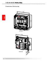
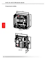
Page 10: ...g Transmit Closing Transmit Opening STOP Opening STOP Closing STATIONARY Opening Closing 1 2 3 TRANSMIT 24V AC DC PE L1 N SK 32 31 120 122 56 Power Stationary Opening Transit Opening Stationary Closing STOP Opening STOP Closing STATIONARY Opening Closing 1 2 3 TRANSMIT 24V AC DC PE L1 N SK 32 33 122 116 18 37 ...

Page 11: ...otective measures 12 3 General 13 4 Proper use 13 5 Device overview 13 5 1 Signal indicators 13 5 2 Connection terminals 13 5 3 Versions and assembly 14 5 4 Connection of multiple sensors per sensor circuit 14 6 Commissioning 14 6 1 Prerequisites 14 6 2 Electrical connection 14 6 3 Example of use 15 7 Troubleshooting 15 8 Taking out of service and disposal 16 9 Technical specifications 16 10 EC de...

Page 12: ...lowed All electrical work must only be performed by skilled electricians All relevant electrical engineering and Employer s Liability Insurance Association safety regulations must be observed During work on the switching unit it is to be switched to zero potential checked to ensure that it is at zero potential and protected against being restarted If the potential free contacts of the relay output...

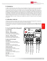
Page 13: ... and beyond these uses constitute improper use The manufacturer assumes no liability for damages arising from improper use The device may only be used in special applications with the manufacturer s express consent 5 Device overview 5 1 Signal indicators LED green Power LED red Stationary Opening Display for sensor Direction of movement Opening channel 1 LED red Stationary Closing Display for sens...

Page 14: ...tal area shall not exceed 10 m2 The maximum size of an ASK is 1350 x 2350 mm The total cable length oft the in series connected ASK must not exceed 25 m Before connecting the sensors that are connected in series it is recommended that the resistance value of the arrangement is to be measured The resistance must be 8 2 kΩ 500 Ω when the sensor is inactive and must not exceed 500 Ω when it is active...

Page 15: ...hmmeter To do this the connection of the sensor to the safety relay must be disconnected and connected to an ohmmeter The resistance must be 8 2kΩ 500 Ω when the sensor is inactive and must not exceed 500 Ω when the sensor is active Circuit diagram in zero potential state Sensor not actuated After the operating voltage is switched on the extinguished red LEDs indicate error free operation If one o...

Page 16: ...ng 122 x 116 x 37 mm Protection class with screw fittings IP65 with blanking plug IP54 Weight 650 g Temperature range 20 C to 55 C Connection cable cross section single or fine stranded cable 0 5 2 5 mm2 Safety category EN ISO 13849 1 2008 Category 3 PL d MTTFd 180 years DC 90 Electronic MTTFd 3757 years Electromechanics B10d 1000000 MTTFd 190 years Nop 52560 8 Taking out of service and disposal T...

Page 17: ...uction as does the version brought to market by us EC machinery directive 2006 42 EC EN ISO 13849 1 2008 EN ISO 13849 2 2008 EN 61000 6 2 2002 EN 61000 6 3 2002 EC type approval Notified Body 0044 TÜV NORD CERT GmbH Langemarckstraße 20 D 45141 Essen EC type approval no 44 205 10 384655 001 This declaration of conformity does not relieve the designer manufacturer of the machine from his obligation ...

Page 18: ...ng Transmit Closing Transmit Opening STOP Opening STOP Closing STATIONARY Opening Closing 1 2 3 TRANSMIT 24V AC DC PE L1 N SK 32 31 120 122 56 Power Stationary Opening Transit Opening Stationary Closing STOP Opening STOP Closing STATIONARY Opening Closing 1 2 3 TRANSMIT 24V AC DC PE L1 N SK 32 33 122 116 18 37 ...

Page 19: ...res de protection 20 3 Généralités 21 4 Utilisation conforme 21 5 Vue d ensemble de l appareil 21 5 1 Indicateurs 21 5 2 Bornes de connexion 21 5 3 Modèles et montage 22 5 4 Raccordement de plusieurs émetteurs de signaux par circuit de signal 22 6 Mise en service 22 6 1 Conditions 22 6 2 Raccordement électrique 22 6 3 Exemple d utilisation 23 7 Recherche d erreurs 23 8 Mise hors service et élimina...

Page 20: ...impérativement être suivies et respectées Les travaux électriques doivent être effectués uniquement par des électriciens professionnels Les prescriptions de sécurité du secteur de l électrotechnique et des associations professionnelles doivent être respectées Lors de travaux sur le relais de sécurité il faut couper la tension vérifier l absence de tension et le protéger contre tout réenclenchement...

Page 21: ...arres palpeuses Un autre emploi n est pas conforme Le fabricant décline toute responsabilité en cas de dommages provenant d une utilisation non conforme Un emploi dans des applications spéciales requiert une validation de la part du fabricant 5 Vue d ensemble de l appareil 5 1 Indicateurs LED verte Power LED rouge Stationary Opening Indication pour l émetteur de signaux sens du mouvement ouverture...

Page 22: ...it pas dépasser 10 m2 Dimensions maximales d un ASK est de 1350 x 2350 mm La longueur maximale des câbles des ASK monter en série ne doit pas dépasser 25 m Avant le raccordement des émetteurs de signaux en série il est recommandé de mesurer la valeur ohmique du câblage Quand l émetteur de signal est au repos la résistance doit être de 8 2 kΩ 500 Ω Si l émetteur de signal est actionnée la résistanc...

Page 23: ...e d un ohmmètre Pour cela coupez la liaison de l émetteur de signaux au relais de sécurité et reliez la à un ohmmètre Quand l émetteur de signaux est au repos la résistance doit être de 8 2kΩ 500 Ω Si l émetteur de signaux est actionné la résistance ne doit pas excéder 500 Ω Schéma de principe dans l état sans courant Capteur non actionné Une fois la tension de service allumée l état éteint des LE...

Page 24: ...Ω Relais Courant nominal CC 3 A 30 V CC Courant nominal CA 3 A 250 V CC Durée de vie mécanique 106 actionnements Temps de commutation du relais de sécurité Temps de réaction 5 ms Temps de déconnexion ca 200 ms Boîtier polycarbonate avec couvercle transparent Dimensions HxLxP Boîtier 120 x 122 x 56 mm presse étoupe M16 incl 140 x 122 x 56 mm n cas de montage sur rail 122 x 116 x 37 mm Indice de pro...

Page 25: ...rité et la santé des directives CE suivantes Directive CE sur les machines 2006 42 CE EN ISO 13849 1 2008 EN ISO 13849 2 2008 EN 61000 6 2 2002 EN 61000 6 3 2002 Examen CE du modèle type Notified Body 0044 TÜV NORD CERT GmbH Langemarckstrasse 20 D 45141 Essen Certificat d examen CE de modèle type n 44 205 10 384655 001 Cette déclaration de conformité ne délie pas le constructeur fabricant de la ma...

Page 26: ...ing Transmit Closing Transmit Opening STOP Opening STOP Closing STATIONARY Opening Closing 1 2 3 TRANSMIT 24V AC DC PE L1 N SK 32 31 120 122 56 Power Stationary Opening Transit Opening Stationary Closing STOP Opening STOP Closing STATIONARY Opening Closing 1 2 3 TRANSMIT 24V AC DC PE L1 N SK 32 33 122 116 18 37 ...

Page 27: ...Generalità 29 4 Uso conforme 29 5 Panoramica 29 5 1 LED di segnalazione 29 5 2 Morsetti di collegamento 29 5 3 Modelli e montaggio 30 5 4 Collegamento di più sensori ad un solo circuito 30 6 Avviamento 30 6 1 Condizioni preliminari 30 6 2 Collegamento elettrico 30 6 3 Esempio di applicazione 31 7 Ricerca dei guasti 31 8 Messa fuori servizio e smaltimento 32 9 Dati tecnici 32 10 Dichiarazione di co...

Page 28: ...nersi e rispettare le avvertenze del presente manuale Solo elettricisti specializzati possono eseguire i lavori elettrici Rispettare le disposizioni di sicurezza dell elettrotecnica e delle associazioni di categoria Prima di sottoporlo ad interventi il relè di sicurezza deve essere scollegato dalla tensione si deve poi verificare l effettiva assenza della tensione ed adottare provvedimenti per imp...

Page 29: ...bordi sensibili di sicurezza Qualsiasi altro uso diverso è considerato non conforme Il produttore declina qualsiasi responsabilità per i danni derivanti da un uso non conforme Per l utilizzo in applicazioni speciali è necessaria l approvazione del produttore 5 Panoramica 5 1 LED di segnalazione LED verde Power LED rosso Stationary Opening Indicatore per sensore Direzione di apertura canale 1 LED r...

Page 30: ... ASK La cui superficie totale non deve superare i 10 m2 Dimensione massima di un ASK è 1350 x 2350 mm La lunghezza totale del cavo di ASK collegati in serie non deve superare i 25 m Prima di collegare i sensori in serie è consigliabile di misurare il valore della resistenza del circuito Con sensori non azionato il valore di resistenza deve essere di 8 2 kΩ 500 Ω Con sensori azionato il valore di r...

Page 31: ...e i sensori mediante un ohmetro A tal fine il collegamento del sensore al relè di sicurezza deve essere interrotto e collegato ad un ohmetro Con sensore non azionato il valore della resistenza deve essere di 8 2kΩ 500 Ω Con sensore azionato il valore di resistenza non deve essere maggiore di 500 Ω Schema elettrico nello stato senza tensione Sensore non azionato Al collegamento della tensione di es...

Page 32: ... guida 122 x 116 x 37 mm Grado di protezione con raccordi filettati IP65 con tappi di chiusura IP54 Peso 650 g Campo di temperatura 20 C 55 C Sezione dei cavi di collegamento conduttore rigido o flessibile 0 5 2 5 mm2 Categoria di sicurezza EN ISO 13849 1 2008 Categoria 3 PL d MTTFd 180 anni DC 90 elettronica MTTFd 3757 anni elettromeccanica B10d 1000000 MTTFd 190 anni Nop 52560 8 Messa fuori serv...

Page 33: ...a salute previsti dalle seguenti direttive CE Direttiva sulle macchine 2006 42 CE EN ISO 13849 1 2008 EN ISO 13849 2 2008 EN 61000 6 2 2002 EN 61000 6 3 2002 Prova di omologazione CE Notified Body 0044 TÜV NORD CERT GmbH Langemarckstraße 20 D 45141 Essen N certificazione prova di omologazione CE 44 205 10 384655 001 La presente dichiarazione di conformità non esonera il progettista produttore dell...

Page 34: ...osing Transmit Closing Transmit Opening STOP Opening STOP Closing STATIONARY Opening Closing 1 2 3 TRANSMIT 24V AC DC PE L1 N SK 32 31 120 122 56 Power Stationary Opening Transit Opening Stationary Closing STOP Opening STOP Closing STATIONARY Opening Closing 1 2 3 TRANSMIT 24V AC DC PE L1 N SK 32 33 122 116 18 37 ...

Page 35: ...heids maatregelen 36 3 Algemeen 37 4 Correct gebruik 37 5 Toesteloverzicht 37 5 1 Signaalweergaven 37 5 2 Aansluitklemmen 37 5 3 Uitvoeringen en montage 38 5 4 Aansluiting van meerdere signaalgevers per signaalgevercircuit 38 6 Inbedrijstelling 38 6 1 Voorwaarden 38 6 2 Elektrische aansluiting 38 6 3 Toepassingsvoorbeeld 39 7 Foutzoeken 39 8 Buitenbedrijfstelling en afvoer 40 9 Technische gegevens...

Page 36: ...ntie De aanwijzingen in deze handleiding moeten absoluut nageleefd worden Elektrische werkzaamheden mogen enkel door elektriciens worden uitgevoerd De veiligheidsvoorschriften betreffende elektrotechniek en die van de bedrijfsvereniging moeten in acht worden genomen Het relais dient bij werkzaamheden hieraan spanningsvrij geschakeld op spanningsvrijheid gecontroleerd en tegen opnieuw inschakelen b...

Page 37: ... veiligheidscontactlijsten Een ander of daarvan afwijkend gebruik geldt als niet correct Voor schade die door een niet reglementair gebruik ontstaat is de fabrikant niet aansprakelijk Voor het gebruik in speciale toepassingen moet de fabrikant toestemming verlenen 5 Toesteloverzicht 5 1 Signaalweergaven LED groen Power LED rood Stationary Opening Indicatie voor signaalgever Bewegingsrichting Opene...

Page 38: ...aximale totale oppervlakte bedraagt niet meer dan 10 m2 Maximale grootte van een ASK is 1350 x 2350 mm De maximale totale kabellengte van in serie geschakelde ASK mag niet groter zijn dan 25 m Voor het aansluiten van de in serie geschakelde signaalgevers is het aan te bevelen om de weerstandswaarde van de schakeling te meten Bij niet geactiveerde signaalgevers moet de weerstand 8 2 kΩ 500 Ω bedrag...

Page 39: ...meettoestel gecontroleerd worden Daarvoor moet de verbinding van de signaal gever naar de veiligheidsrelais losgemaakt en met een weerstandsmeettoestel verbonden worden Bij niet geactiveerde signaalgever moet de weerstand 8 2kΩ 500 Ω bedragen Als de signaalgever geactiveerd is mag de weerstand 500 Ω niet overschrijden Na het inschakelen van de bedrijfsspanning tonen de gedoofde rode LED s het stor...

Page 40: ...eschermingsklasse met schroefverbindingen P65 met afsluitstop IP54 Gewicht 650 g Temperatuurbereik 20 C tot 55 C Diameter aansluitleidingen een of fijndradige leiding 0 5 2 5 mm2 Veiligheidscategorie EN ISO 13849 1 2008 categorie 3 PL d MTTFd 180 jaar DC 90 Electronics MTTFd 3757 jaar Electromechaniek B10d 1000000 MTTFd 190 jaar Nop 52560 8 Buitenbedrijfstelling en afvoer De producten die door ASO...

Page 41: ...heidseisen uit de volgende EG richtlijnen en normen EG machinerichtlijn 2006 42 EG EN ISO 13849 1 2008 EN ISO 13849 2 2008 EN 61000 6 2 2002 EN 61000 6 3 2002 EG typeonderzoek Notified Body 0044 TÜV NORD CERT GmbH Langemarckstraße 20 D 45141 Essen EG typegoedkeuringscertificaatnr 44 205 10 384655 001 Deze verklaring van overeenstemming ontbindt de constructeur fabrikant van de machine niet van zij...

Page 42: ...Closing Transmit Closing Transmit Opening STOP Opening STOP Closing STATIONARY Opening Closing 1 2 3 TRANSMIT 24V AC DC PE L1 N SK 32 31 120 122 56 Power Stationary Opening Transit Opening Stationary Closing STOP Opening STOP Closing STATIONARY Opening Closing 1 2 3 TRANSMIT 24V AC DC PE L1 N SK 32 33 122 116 18 37 ...

Page 43: ...43 Notizen Notes Notes Note Notities ...

Page 44: ...ques Nous déclinons toute responsabilité en cas d erreurs et de fautes d impression 11 DB 09 011 Dati tecnici Rev 10 Con riserva di modifiche tecniche Si declina qualsiasi responsabilità per errori ed errori di stampa 11 DB 09 011 Technische gegevens Rev 10 Technische wijzigingen voorbehouden Wij zijn niet aansprakelijk voor vergissingen en drukfouten Deutsch English Français Italiano Nederlands A...

Reviews: