background image

Asoka® User Guide  
PlugLink PL7667-ETH 

Page 2 of 33 

THE SPECIFICATIONS AND INFORMATION REGARDING THE PRODUCTS IN THIS MANUAL ARE 
SUBJECT TO CHANGE WITHOUT NOTICE. ALL STATEMENTS, INFORMATION, AND 
RECOMMENDATIONS IN THIS MANUAL ARE BELIEVED TO BE ACCURATE BUT ARE PRESENTED 
WITHOUT WARRANTY OF ANY KIND, EXPRESSED OR IMPLIED. USERS MUST TAKE FULL RESPONSIBILITY 

FOR THEIR APPLICATION OF ANY PRODUCTS. 
 

THE SOFTWARE LICENSE AND LIMITED WARRANTY FOR THE ACCOMPANYING PRODUCT ARE SET 
FORTH IN THE INFORMATION PACKET THAT SHIPPED WITH THE PRODUCT AND ARE INCORPORATED 
HEREIN BY THIS REFERENCE. IF YOU ARE UNABLE TO LOCATE THE SOFTWARE LICENSE OR LIMITED 
WARRANTY, CONTACT YOUR ASOKA REPRESENTATIVE FOR A COPY. 

 
The following information is for FCC compliance of Class A devices: This equipment has been 
tested and found to comply with the limits for a Class A digital device, pursuant to part 15 of the 

FCC rules. These limits are designed to provide reasonable protection against harmful 
interference when the equipment is operated in a commercial environment. This equipment 
generates, uses, and can radiate radio-frequency energy and, if not installed and used in 
accordance with the instruction manual, may cause harmful interference to radio 
communications. Operation of this equipment in a residential area is likely to cause harmful 

interference, in which case users will be required to correct the interference at their own 
expense. 
 

Modifying the equipment without Asoka’s written authorization may result in the equipment no 
longer complying with FCC requirements for Class A digital devices. In that event, your right to 
use the equipment may be limited by FCC regulations, and you may be required to correct any 

interference or radio or television communications at your own expense. 
 

You can determine whether your equipment is causing interference by turning it off. If the 

interference stops, it was probably caused by the Asoka equipment or one of its peripheral 
devices. If the equipment causes interference to radio or television reception, try to correct the 

interference by using one or more of the following measures: 
 

ƒ


Turn the television or radio antenna until the interference stops. 

ƒ


Move the equipment to one side or the other of the television or radio. 

ƒ


Move the equipment farther away from the television or radio. 

ƒ


Plug the equipment into an outlet that is on a different circuit from the television or radio. 
(That is, make certain the equipment and the television or radio is on circuits controlled by 

difference circuit breakers or fuses.) 

 
Modifications to this product not authorized by Asoka could void the FCC approval and negate 
your authority to operate the product. 

 
NOTWITHSTANDING ANY OTHER WARRANTY HEREIN, ALL DOCUMENT FILES AND SOFTWARE OF 
THESE SUPPLIERS ARE PROVIDED “AS IS” WITH ALL FAULTS. ASOKA DISCLAIM ALL WARRANTIES, 

EXPRESSED OR IMPLED, INCLUDING, WITHOUT LIMITATION, THOSE OR MERCHANTABILITY, FITNESS 
FOR A PARTICULAR PURPOSE AND NONINFRINGEMENT OR ARISING FROM A COURSE OF DEALING, 
USAGE OR TRADE PRACTICE. 


Summary of Contents for Plugline PL7667-ETH

Page 1: ...PlugLine Smart Energy AV Ethernet 66 0366 01Rev 003 User s Guide PL7667 ETH...

Page 2: ...r own expense Modifying the equipment without Asoka s written authorization may result in the equipment no longer complying with FCC requirements for Class A digital devices In that event your right t...

Page 3: ...ECT SPECIAL CONSEQUENTIAL OR INCIDENTAL DAMAGES INCLUDING WITHOUT LIMITATION LOST PROFITS OR LOSS OR DAMAGE TO DATA ARISING OUT OF THE USE OF INABILITY TO USE THIS MANUAL EVEN IF ASOKA HAVE BEEN ADVIS...

Page 4: ...Safety Instructions for the PlugLink 7 3 Overview 8 4 Installation 11 5 Getting Started with the PlugLink 15 6 Basic PL7667 MST Configuration 19 7 PL7667 MST Administration 22 8 Reset and network of...

Page 5: ...scriptions use the following conventions Commands and keywords are in italic text Arguments for which you supply values are in bold Square brackets indicate optional elements Braces group require choi...

Page 6: ...this URL http www asokausa com Document Feedback You can submit comments via email to custserv asokausa com You can also submit your comments via regular mail by writing to the following address Asok...

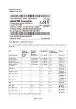
Page 7: ...ions before installing and operating this product Do not open the cover on this product and or alter this product in any way Follow common household electrical safety practices If you have any questio...

Page 8: ...T Ethernet port Status LEDs showing Ethernet activity and link status Up to 200Mbps of data transmission Energy control Package Contains Open the package and check that you have all the following ite...

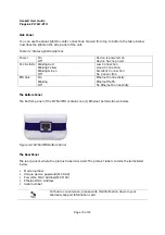
Page 9: ...Asoka User Guide PlugLink PL7667 ETH Page 9 of 33 Figure 3 1 PL7667 ETH Top Panel The Front Panel The front panel of the PL7667 contains the one Power Outlet Figure 3 2 PL7667 ETH Front Panel...

Page 10: ...on Excellent Connection No Connection ETH Link On Blinking Off Ethernet Connectivity Ethernet Traffic No Ethernet Connectivity The Bottom Panel The bottom panel of the PL7667 ETH contains one 1 Ethern...

Page 11: ...above 7 x Opera 7 Windows XP 5 5 or above 1 x or above 7 x Opera 7 Windows 2003 Server 5 5 or above 1 x or above 7 x Opera 7 Windows NT 4 0 5 5 or above 1 x or above 7 x Opera 7 RedHat 6 2 1 0 7 x Ope...

Page 12: ...o disable the popup blocker follow these steps Under Internet Explorer 1 Open a web browser 2 Under the Tools menu select Turn off Popup Blocker Under Firefox or Netscape 1 Open a web browser 2 Under...

Page 13: ...over or otherwise dismantling the unit voids the warranty Warnings Only trained and qualified personnel should be allowed to install or replace this equipment Read the installation instructions before...

Page 14: ...ople cannot step on it Do not place anything over the Ethernet cord Disconnect this equipment from the power outlet before cleaning it Do not use liquid or sprayed detergent for cleaning Use moisture...

Page 15: ...PE directly to a power outlet without mounting screws and brackets The CPE can be simply plugged in directly to a power outlet If you do not wish to physically mount the CPE onto the power outlet foll...

Page 16: ...see Chapter 4 Installation For product overview information see Chapter 3 Overview Connecting to a PC To perform the initial configuration follow these steps 1 Connect a Category 5 straight through c...

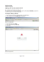
Page 17: ...n your PC an IP address of 192 168 1 x where x is a number between 1 and 254 excluding 253 Accessing the CPE from your Browser 1 Open an Internet browser i e Internet Explorer or Mozilla Firefox 2 In...

Page 18: ...apter 7 Understanding the PL7667 ETH Web Interface When you access the web based user interface UI the System Details page is the first page you will see The System Details page shows you a quick view...

Page 19: ...ils page 2 The Glossary button is available in every page of the UI Pressing this button will take you to a glossary page that defines many of the technical terms used in this UI 3 The Help button is...

Page 20: ...meters of your PL7667 interface including IP Subnet Mask and DNS settings This chapter contains the following sections LAN Settings Configuring your LAN Settings To configure the CPE s LAN settings cl...

Page 21: ...choose should be a non routable IP Examples of a non routable IP are 192 168 x x where x is anything between 0 and 255 10 x x x where x is anything between 0 and 255 2 Subnet Mask A Subnet Mask allow...

Page 22: ...a User Guide PlugLink PL7667 ETH Page 22 of 33 Figure 6 2 Device Scan Screen The Device Scan screen will only list Powerline devices on your network that have the same Powerline Network Encryption KEY...

Page 23: ...rly Rebooting will not delete any of your configuration settings To reboot the adapter 1 Click on Systems in the Main menu 2 In the Sub menu select Reboot System 3 Click Reboot 4 A popup window will a...

Page 24: ...o factory default settings To restore factory default settings 1 Click on Systems in the Main menu 2 On the Sub menu select Factory Reset 6 Click Restore Default 7 A popup window will appear to confir...

Page 25: ...in the Main menu 2 In the Sub menu select Update Firmware 3 Click Browse to locate the new firmware update file downloaded from Asoka s web site 4 The box next to the Browse button will now display t...

Page 26: ...Asoka User Guide PlugLink PL7667 ETH Page 26 of 33 Figure 7 3 Firmware upgrade screen...

Page 27: ...vice A and plug into an AC outlet The POWER light indicator should be lit solid green a Press the SECURITY button BRIEFLY 1 second and release The POWER light should now be blinking green b IMPORTANT...

Page 28: ...PORTANT If the POWER light is not blinking green repeat Step a until the power light is blinking green c This unit is now ready to join the existing HD AV network This unit will remain in this adder m...

Page 29: ...his process per device 5 Congratulations you are done Figure 8 2 Three devices of PLC Notes 1 The other devices already in the Power line network with the proper NEK are not affected and do not need t...

Page 30: ...30 of 20 Appendix A Default Settings Login and Password User Name admin Password welcome IP Setting IP Address 192 168 1 254 Subnet Mask 255 255 255 0...

Page 31: ...ent off and on the user is encouraged to try to correct The interference by one or more of the following measures Reorient or relocate the receiving antenna Increase the separation between the equipme...

Page 32: ...Asoka USA Corporation 2620 Augustine Drive Suite 230 Santa Clara CA 95054 USA Phone 408 550 8167 Fax 408 884 2390 www asokausa com URL www asokatech com...

Reviews: