background image

Asoka® User’s Guide 
PlugLink® 9850 IP Camera PL9850-CMS 


32

Chapter 9 


Configuring the PlugLink 9850 for Remote Access 
 
Dynamic DNS Setup 

 
DSL/Cable ISPs generally provide dynamic IP addresses to their customers.  This 
means an IP address that is assigned to a customer is temporary and will change after 
a certain period of time.   This causes problems for users who wish to access their 
networks remotely.  To work around this, users will need to sign up for Dynamic DNS 
services: 


Dynamic DNS solves the above-mentioned problem and allows users to 
connect to their networks through a user-selected domain name even though 
they have a dynamic IP address.    Users will need to sign up for service through 
one of the Dynamic DNS service providers.     


Once you have signed up for service you need to configure a Dynamic DNS 
updater application which will report any changes in your IP address to your 
Dynamic DNS provider.  The PlugLink 9850 IP Camera provides a built-in 
updater application which can be used.  Selected models of DSL/Cable 
routers also provide this capability.     


NOTE: 

Dynamic DNS providers recommend software updaters be used.  

Please check with your provider for their recommended selections if this is 
what you want to do.   


Regardless of the method you choose, you will need to configure the updater 
application.  Generally this will include your user name, password and your 
selected domain name 

(

eg:

 mycamera.dyndns.org)

.    Once this is complete, 

please read on for more information on setting remote access to your IP 
camera(s). 


Camera Setup 
 

To configure the PlugLink 9850 IP Camera for Internet access to the web-based utility, 
please read the following: 


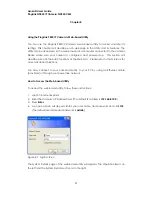
Log into the PlugLink 9850 IP Camera’s Web-based utility from your local 
network.  


Click on the 

Network

 button. 


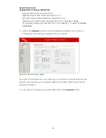
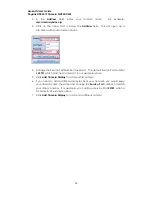
Change the Web Server Port of the PL9850 IP Camera from the default of 

80

 to 

another number.  As an example only, let’s use 

Port 81.  

Click 

Apply

 to 

accept the changes and reboot your camera.     


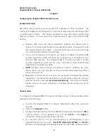
You will then need to set up port-forwarding or port-mapping on your 
Cable/DSL Router for two ports:  

Port 23721 (default for PL9850) 

and 

Port 81

.  

Set the port-forwarding/port-mapping to send any TCP traffic on these ports to 

Summary of Contents for PlugLink PL9850-CMS

Page 1: ...uide PlugLink 9850 IP Camera PL9850 CMS 2007 Asoka USA Corporation Asoka PlugLink and the Asoka logo are registered trademarks or trademarks of Asoka USA Corporation Information is subject to change without notice All rights reserved PL9850 CMS 041907 PN 66 0316 010 ...

Page 2: ...necting the PlugLink 9850 for Setup 11 5 Installing and Configuring the PlugLink IP Camera 12 6 Placement Options 20 7 Using the PlugLink 9850 IP Camera Utility 21 8 Using the PlugLink 9850 Web based Utility 27 9 Configuring the PlugLink 9850 for Remote Access 32 10 Technical Support Information 35 11 Glossary 36 12 Technical Specifications 38 13 FCC Statement 39 14 Warranty Information 40 ...

Page 3: ...ra into any power outlet instantly providing a home monitoring solution for your home and office The PlugLink 9850 will not interfere with other household appliances such as hair dryers vacuum cleaners or microwave ovens Consuming only 5 watts of power it is environmentally friendly and will not noticeably increase your electrical bill It is a simple and reliable choice for those wishing to add su...

Page 4: ... unit When you operate the camera the power outlet should be near the camera and easily accessible Do not open the cover or casing on this product and or alter this product in any way Follow common household electrical safety practices Refer all servicing to qualified service personnel Servicing is required when the unit has been damaged in any way such as the AC adapter cord or plug is damaged th...

Page 5: ...incorrect missing or damaged contact the retailer where you made your purchase Keep the carton including the original packing materials in case you need to return the unit for repair The Front Panel The front panel of the PL9850 CMS contains the LENS of the camera and the FOCUS KNOB Figure 3 1 PL9850 CMS Front Panel To focus the lens turn the FOCUS KNOB The Right Panel The status light is located ...

Page 6: ...ndicates Ethernet connectivity Figure 3 2 PL9850 CMS Right Side Panel The Rear Panel The rear panel features two ports POWER The POWER port is where you will connect the power adapter ETHERNET The ETHERNET port is where you will connect the Ethernet network cable Figure 3 3 PL9850 CMS Rear panel The Product label on the back of the PL9850 CMS displays the following Product name Model number ...

Page 7: ...ill press if you need to reset the camera Using a long thin object such as a stylus or the end of a straightened paper clip press the RESET button and hold it in for five seconds Note Resetting the camera will erase all of your settings Do not reset the camera if you want to retain your configuration settings The below table lists the factory default settings of the camera Table 3 2 Factory Defaul...

Page 8: ...Asoka User s Guide PlugLink 9850 IP Camera PL9850 CMS 8 Figure 3 5 Bottom panel of the PL9850 CMS ...

Page 9: ...rent points Please see Chapter 4 Placement Options for more on mounting your camera to the wall Figure 3 6 Mounting to the wall diagram Pan Tilt Operation Pan Tilt scan buttons automatically move the lens horizontally from 60 to 60 and vertically from 45 to 45 and return the lens to its original position Each corresponding pan tilt arrow moves the lens Up Down Right or Left and the home position b...

Page 10: ... PL9850 CMS 10 Figure 3 7 Pan Tilt Camera Note Pan Tilt operation must be controlled only by pressing the control buttons Do not apply external pressure to the pan tilt portion of the camera Any forced movement can damage the internal mechanism ...

Page 11: ...move the camera from a wired network to a power line network please reference the section below Moving the Camera to a Power Line Network If you do not require changing your network type proceed directly to Chapter 5 Installing and Configuring the PlugLink 9850 IP Camera Moving the Camera to a Power Line Network When you move the Camera from a wired network to a power line network or vice versa yo...

Page 12: ...degrade the performance of your camera 1 Insert the enclosed Installation Resource CD into your CD ROM drive The Installation Utility should appear automatically If it does not appear within 30 seconds select your CD ROM drive and double click on the icon named Setup exe to initiate the Installation Utility 2 The Welcome screen should appear Click on Setup Assistant to proceed to installation Figu...

Page 13: ...r s Guide PlugLink 9850 IP Camera PL9850 CMS 13 Figure 5 2 Beginning the Installation Process 5 Please read the license agreement carefully and click on the Agree button to continue Figure 5 3 License Agreement ...

Page 14: ...iven fields If you wish to have a router automatically assign an IP Address to your camera you may select DHCP Note DHCP is recommended Static IP is ideal for more advanced users Figure 5 4 DHCP Configuration 7 PPPoE Configuration If you have a DSL connection you may use PPPoE Configuration function to connect to your ISP As broadband routers also provide this function using this feature is option...

Page 15: ...omatically using this feature is optional Figure 5 6 DNS Configuration 9 DDNS configuration DDNS allows you to assign a domain name to a dynamic IP address If you have an existing DDNS account or service select Yes and enter your information in the provided fields Otherwise please select No If you wish to learn more about DDNS please contact a DDNS service provider Figure 5 7 DDNS Configuration ...

Page 16: ...he provided fields Otherwise please select No User ID and Password are both case sensitive and space sensitive Figure 5 8 DNS Configuration 11 Camera Name The default camera name is Asoka Camera The name is both case sensitive and space sensitive If you wish to change the name of the camera to something more descriptive e g Living Room select Yes and enter the new camera name Otherwise please sele...

Page 17: ...e provided field Otherwise please select No Please note that in order to operate correctly the camera s NEK must match the NEK of other devices in your power line network Figure 5 10 NEK configuration 13 Please select a location to install the software and click on the Install button to continue Figure 5 11 Select the location to install the PlugLink 9850 Camera Utility ...

Page 18: ...a User s Guide PlugLink 9850 IP Camera PL9850 CMS 18 14 Please click Begin to start the installation process Figure 5 12 Select Begin to begin installation 15 The drivers and utility files will be installed ...

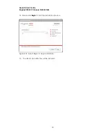
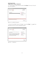
Page 19: ...e been installed please click Continue to proceed to the next step of the installation Figure 5 13 Installation Complete 17 Once the installation has been complete please click Close to complete the installation process and close the installation program Figure 5 14 Finishing Up ...

Page 20: ...o the three available holes on the base unit 2 Connect and secure the head connecter to the base unit 3 Connect the head to the back of the camera 4 Optionally you can use the included I shaped bracket extension for longer reach Wall Option 2 1 Secure the base onto the wall by inserting three screws into the three available holes on the base unit 2 Connect the L shaped bracket to the base unit Mak...

Page 21: ...the drivers for the PlugLink 9850 IP Camera If you are using the utility internally please be sure that the computer you are running the utility from is on the same power line network as the IP Cameras It must also have the same IP subnet and Network Encryption Key NEK There are two ways to open the PlugLink 9850 IP Camera Utility 1 Double click the icon on your desktop the icon acts as a shortcut...

Page 22: ...he Network Camera Utility should automatically detect the cameras and list the IP addresses of any cameras that are on the network Highlight and select one of the IP addresses Note If there are any cameras that have been set up but do not show up on the list you can manually enter the IP address and see if the utility will pick it up If you click on the small arrow below the Address field you will...

Page 23: ... these settings you may log into the PlugLink 9850 s Web based utility B Add Camera Display Clicking on a viewing window and clicking the Add Camera Display button displays the camera listed in the Address field on the corresponding viewing window Note Double click anyone of the viewing window to enlarge the picture C Close Current Camera Clicking the Close Current Camera closes the viewing window...

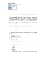
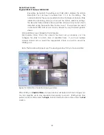
Page 24: ... format and can be viewed by any standard graphic viewer L Save Bitmap saves images to the computer M Capture Video Once the camera has been set up properly you can configure the utility to record video at specified times If you have multiple camera screens set up select the appropriate screen you wish to record by clicking on it Note The blue bar will appear over the viewing window that you have ...

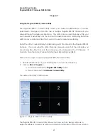
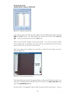
Page 25: ... record another screen simply click on the screen you wish to record and repeat the process above Each screen has its own timer to record videos When the videos are recording you will notice a red dot in the screens as shown below in Figure 7 5 Figure 7 5 Video Capture Indicator The videos will be recorded at the pre set times you have selected and saved to your hard drive for later review By defa...

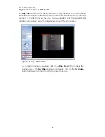
Page 26: ...corner of the utility Use them as needed to review the video that was created Also the recording time and date will be displayed in the upper hand corner of the video screen Figure 7 6 Play Video Screen If you need to review other videos click on the Stop Video button to clear the current video The Play Video button will reappear Click on the Play Video button and select another video that you nee...

Page 27: ... the Web GUI Please refer to the Glossary for more advanced functions You may connect to your camera directly to your PC by using an Ethernet cable provided or through your power line network How to Access the Web based Utility To access the web based utility follow these instructions 1 Launch Internet Explorer 2 Enter the Camera s IP Address field The default IP address is 192 168 8 100 3 Press E...

Page 28: ...850 IP Camera PL9850 CMS 28 Figure 8 2 Systems Details page Using the Operation Bar The Operation Bar is organized into four main sections Motor Control Video Control Capture and Record and System Functions Figure 8 3 Operation Bar ...

Page 29: ...y tilt up and down C Tilt the camera up D Automatically pan up down left and right E Tilt the camera right F Tilt the camera down G Tilt the camera left Video Control Figure 8 5 Video Control H Autobright Allows the camera to auto adjust brightness and contrast I Contrast Adjust the video contrast from 0 to 31 J Brightness Adjust video brightness from 0 to 31 K Saturation Adjust video saturation f...

Page 30: ...e from 0 to 3 0 160x120 1 176x144 2 320x240 3 640x480 5 Click on the Network button to access the Network settings for the IP Camera Change any of the settings as needed to fit your network Figure 8 6 Network setup page If you plan to install more than one camera in your network and access them from the Internet you should give each camera a different IP Address Web Service Port and Service Port n...

Page 31: ...iew the section dedicated to the PlugLink 9850 IP Camera Utility in the previous chapter Chapter 7 Using the PlugLink 9850 IP Camera Utility 7 If you wish to grant regular users access to viewing the camera in the Web GUI you can have users login by using the default user name password of user user This mode will allow users to view the camera but not alter the configuration of the camera Note If ...

Page 32: ... can be used Selected models of DSL Cable routers also provide this capability NOTE Dynamic DNS providers recommend software updaters be used Please check with your provider for their recommended selections if this is what you want to do Regardless of the method you choose you will need to configure the updater application Generally this will include your user name password and your selected domai...

Page 33: ...ollowing From the Internet enter the domain name you selected when you signed up for Dynamic DNS service and the Web Server port number in Internet Explorer For example if you chose the domain name mycamera dyndns org and wish to access Camera 1 you would enter http mycamera dyndns org 81 into your Internet Explorer window Your DSL Cable router should forward the packets to your camera and you sho...

Page 34: ...ice Port Number if needed The default Service Port Number is 23721 which matches Camera 1 in our example above 5 Click Add Camera Display to add your first camera 6 If you need to add additional cameras from your network you would keep your domain name the same and change the Service Port number to match your other cameras For example you could use Service Port 23722 which is for Camera 2 example ...

Page 35: ...HAT WAS SHIPPED WITH YOUR PRODUCT By registering your product at www asokausa com register we can provide you with faster expert technical support and timely notices of product and software upgrades Support Information Support hours are 6am 6pm pst Monday thru Friday excluding U S Holidays Phone 1 888 ASOKAUSA Email support asokausa com URL www asokausa com ...

Page 36: ...e static IP address listed in the IP Address field ENABLE PPPoE This allows you to set up your PlugLink 9850 Camera to use PPPoE instead of having a static IP or getting an IP dynamically Enter the settings as needed to configure your PPPoE session GATEWAY This will typically provide the IP address of a router that is connected to a Cable or DSL modem Please input the IP address accordingly IP ADD...

Page 37: ...taken to the System Log screen From here you can view all the activity associated with your Camera WEB SERVER PORT By default this port is used to allow access to the Web GUI This can be changed as needed UPGRADE If you click on the Upgrade button you will be taken to the Update Firmware screen You can download the latest firmware from the Asoka website and upgrade it here Simply click on the Brow...

Page 38: ...ontrast Hue Saturation Quality Video Adjustment etc VGA 640x480 QVGA 320x240 Up to 20 fps Jpeg and motion Jpeg Max 50 Network connections simultaneously Pan X Y control Remote reset Processor 32 Bits RISC Embedded cache 8K byte I cacha 2K D cache ARM7TDMI base RISC 80MHz default Memory 2 MBytes NOR Flash 8 MBytes SDRAM Bandwidth Up to 85 Mbps Operating Frequency 4 to 21 MHz Modulation Schemes Orth...

Page 39: ... the equipment off and on the user is encouraged to try to correct the interference by one or more of the following measures Reorient or relocate the receiving antenna Increase the separation between the equipment and receiver Connect the equipment into an outlet on a circuit different from that to which the receiver is connected Consult the dealer or an experienced radio TV technician for help Th...

Page 40: ...e of the product This warranty extends only to you the original purchaser and is not transferable to any subsequent purchasers Warranty is void on products purchased or used outside the United States This warranty does not apply if in the judgment of Asoka the product fails due to damage from shipment handling storage accident abuse misapplication or misuse or if it has been used or maintained in ...

Page 41: ... ANY PERSON OR ENTITYFOR ANY SPECIAL INCIDENTAL INDIRECT OR CONSEQUENTIAL DAMAGES INCLUDING WITHOUT LIMITATION DAMAGES RESULTING FROM THE USE OR MALFUNCTION OF THE PRODUCTS LOSS OF PROFITS OR REVENUES BUSINESS INTERRUPTION OR COSTS OF REPLACEMENT GOODS EVEN IF ASOKA IS INFORMED IN ADVANCE OF THE POSSIBILITY OF SUCH DAMAGES ...

Page 42: ...s Guide PlugLink 9850 IP Camera PL9850 CMS 42 Asoka USA Corporation 558 Pilgrim Drive Ste H Foster City CA 94404 Sales 650 286 1700 sales asokausa com Support 888 ASOKAUSA support asokausa com URL www asokausa com ...

Reviews: