EFD1000 E5 Dual Electronic Flight Instrument (EFI) Install Manual
DOCUMENT # 900-00041-001
PAGE 113-226
REVISION D
© Copyright 2019 Aspen Avionics Inc.
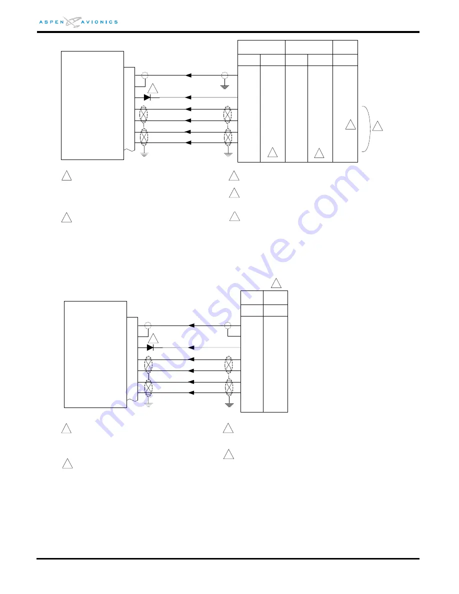
Figure 9-15: Analog NAV Interface
ACU
1
NAV Composite
P401
P901
A2
A1
H
_
KX155/165 Nav units have dual GS outputs. Use
“Numbered” or Lettered pins, not both. Use unused
pins independent from those driving a backup NAV
indicator if possible. Otherwise parallel as close to
NAV receiver as possible (see Figure 9-24 & 9-25)
KX155
KX165
KX155A
KX165A
20
2
32
13
31
12
H
8
8
15 - S
15 - S
14 - R
17 - U
16 - T
17 - U
14 - R
16 - T
_
_
_
_
_
_
_
_
_
_
Composite GND
/ILS Engage
GS +UP
GS +DN
GS -FLG
GS +FLG
1
1
1
ACU
1
NAV Composite
P532
P1
B
KN-53
SL-30
20
2
32
13
31
12
12
15
32
28
31
13
14
P
R
Composite GND
/ILS Engage
GS +UP
GS +DN
GS -FLG
GS +FLG
1
30
33
37
19
2
2
Glideslope interface is for units with GS option.
3
P2
P2
KX170A/
170B/175B
P171
3
4
See manufacturers’ documentation for
KN-70/73/75 Glideslope connections.
3
_
_
_
_
_
4
2
2 See Figure 9-27 for SL-30 configuration.
If paralleling GS signals with backup NAV indicator
then splice wires as close to NAV receiver as
possible. Do not parallel at back of NAV indicator
(see Figures 9-24 & 9-25)
3
4
Diode required when paralleling ILS Energize wire
with backup NAV indicator. See Figure 9-24. Use
1N4005.
5
4
Diode required when paralleling ILS Energize wire
with backup NAV indicator. See Figure 9-24. Use
1N4005.
Refer to manufacturers’ documentation to verify the
integration data and for information regarding
checkout procedures. This drawing, as it pertains to
the non-Aspen equipment, is for reference only.
3
Refer to manufacturers’ documentation to verify the
integration data and for information regarding
checkout procedures. This drawing, as it pertains to
the non-Aspen equipment, is for reference only.


